
Board assembly, optical transceiver using same and method for mounting same on object

a technology of optical transceivers and boards, applied in the direction of optics, optical elements, instruments, etc., can solve the problems of increasing the risk of causing the strain the use of unnecessary force, and the increase of the stress of leads or the misalignment of the optical axis. to achieve the effect of relaxing the stress of flexible boards

Inactive Publication Date: 2006-11-16
HITACHI CABLE
View PDF4 Cites 45 Cited by
  • Summary
  • Abstract
  • Description
  • Claims
  • Application Information

AI Technical Summary

Benefits of technology

"The invention provides a board assembly and an optical transceiver that can relax stress on the flexible board, which can cause problems like strain on the leads and misalignment of the optical axis. The invention solves this problem by preforming the flexible board with a curved portion that matches the desired curvature change, and mounting the first and second rigid boards in different positions. The flexible board can also be bent once at a space lower than the second rigid board, and the curved portion of the flexible board can have a gradual change in curvature to match the predetermined inner angle between the first and second rigid boards. The invention also includes a method for mounting the board assembly on electronic / optoelectronic devices. Overall, the invention provides a solution for relaxing stress on the flexible board and improving the reliability of the optical transceiver."

Problems solved by technology

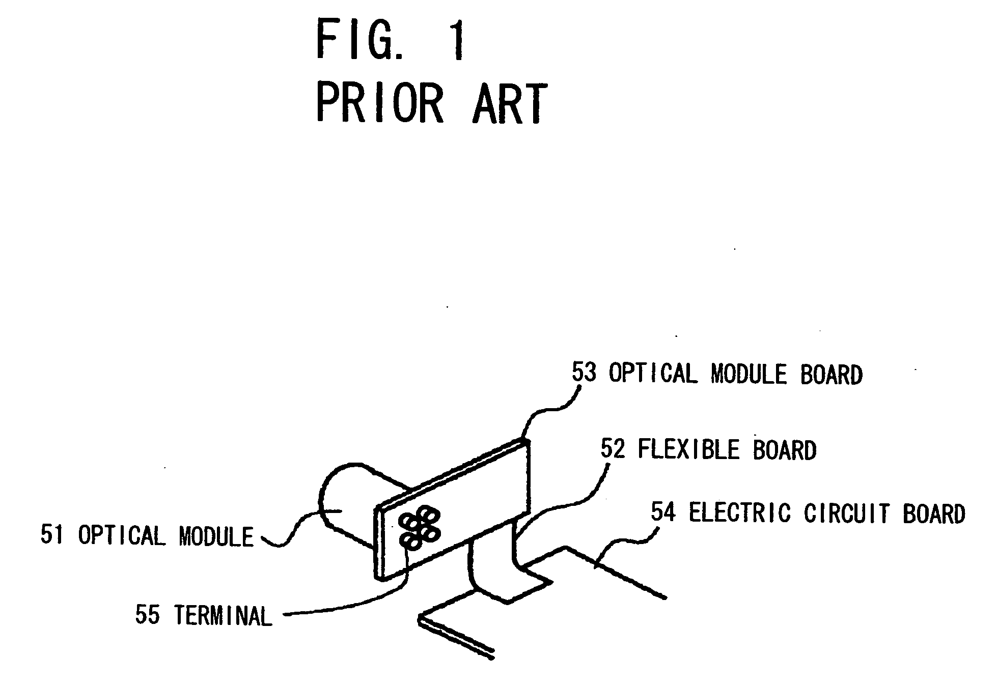
Since the optical module 51 receives this repulsive force, a risk of causing the strain of the leads or the misalignment of the optical axis of the optical module cannot be completely overcome.
In addition, it is a complicated operation to apply the bending force to the flexible board 52 while carrying the board assembly into the housing, and it is inevitable to apply unnecessary force to the optical module 51, or to each of the first and second rigid boards 53, 54 during this process.
Therefore, the aforementioned problems of the strain of the leads or misalignment of the optical axis become more serious.

Method used


Image

  • Board assembly, optical transceiver using same and method for mounting same on object
  • Board assembly, optical transceiver using same and method for mounting same on object
  • Board assembly, optical transceiver using same and method for mounting same on object

Examples


Embodiment Construction

[0049] Preferred embodiments of the present invention will be explained in detail hereinafter with referring to the appended drawings.

[0050]FIG. 3 is a side view showing a board assembly in the first preferred embodiment according to the invention.

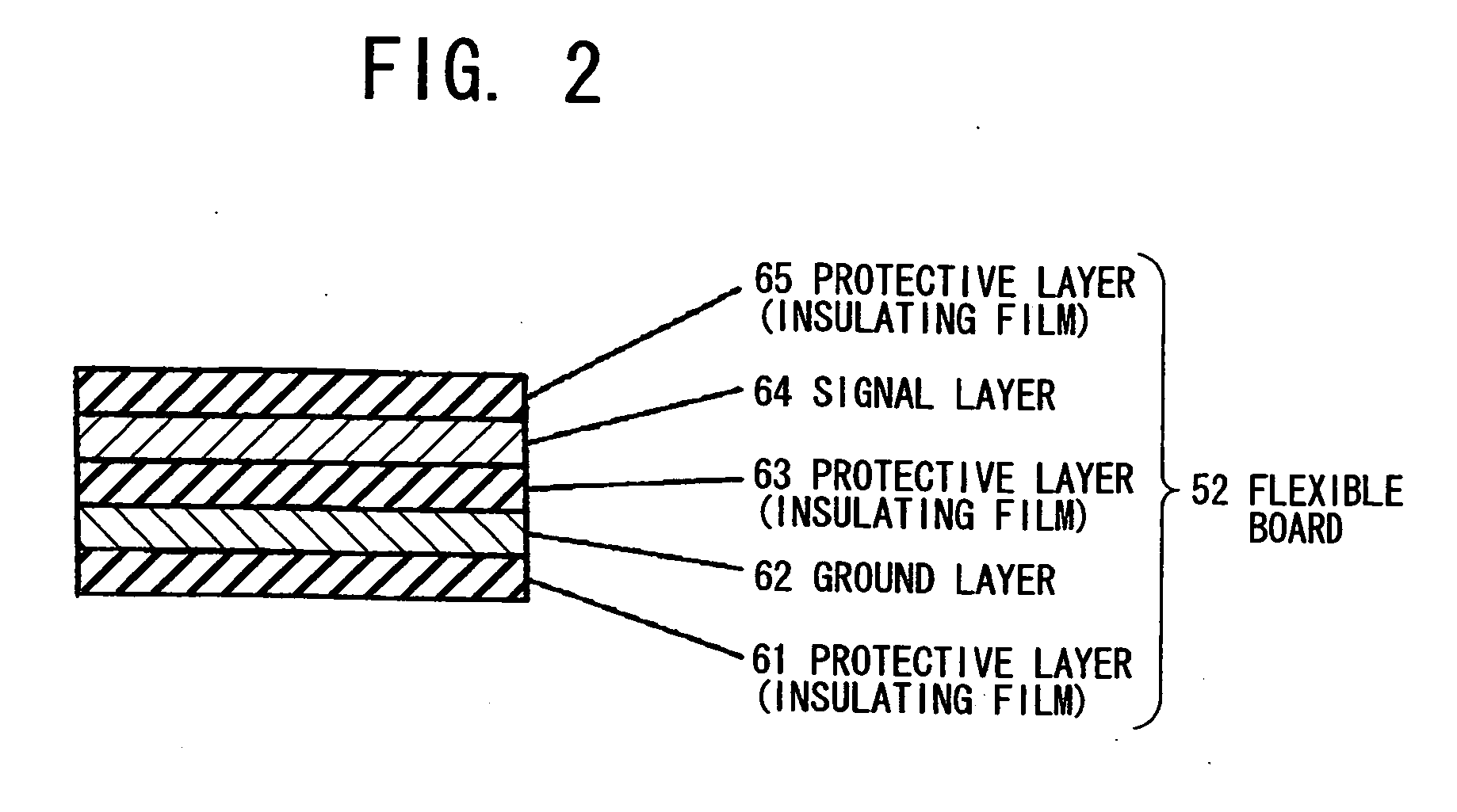
[0051] As shown in FIG. 3, a board assembly 1 in the first preferred embodiment according to the invention comprises a flexible board 2, a first rigid board 3, and a second rigid board 4. The first rigid board 3 and the second rigid board 4 connected with each other by the flexible board 2 are mounted on each object (not shown) in different positions. The flexible board 2 is preformed to have a configuration shown in FIG. 3. The flexible board 2 comprises a signal layer, a ground layer and insulating layers. Further, so as to distinguish the first rigid board 3 and second rigid board 4, the first rigid board 3 and the second rigid board 4 are hereinafter referred as “optical module board 3” and “electric circuit board 4”, respectively, b...


PUM


Abstract

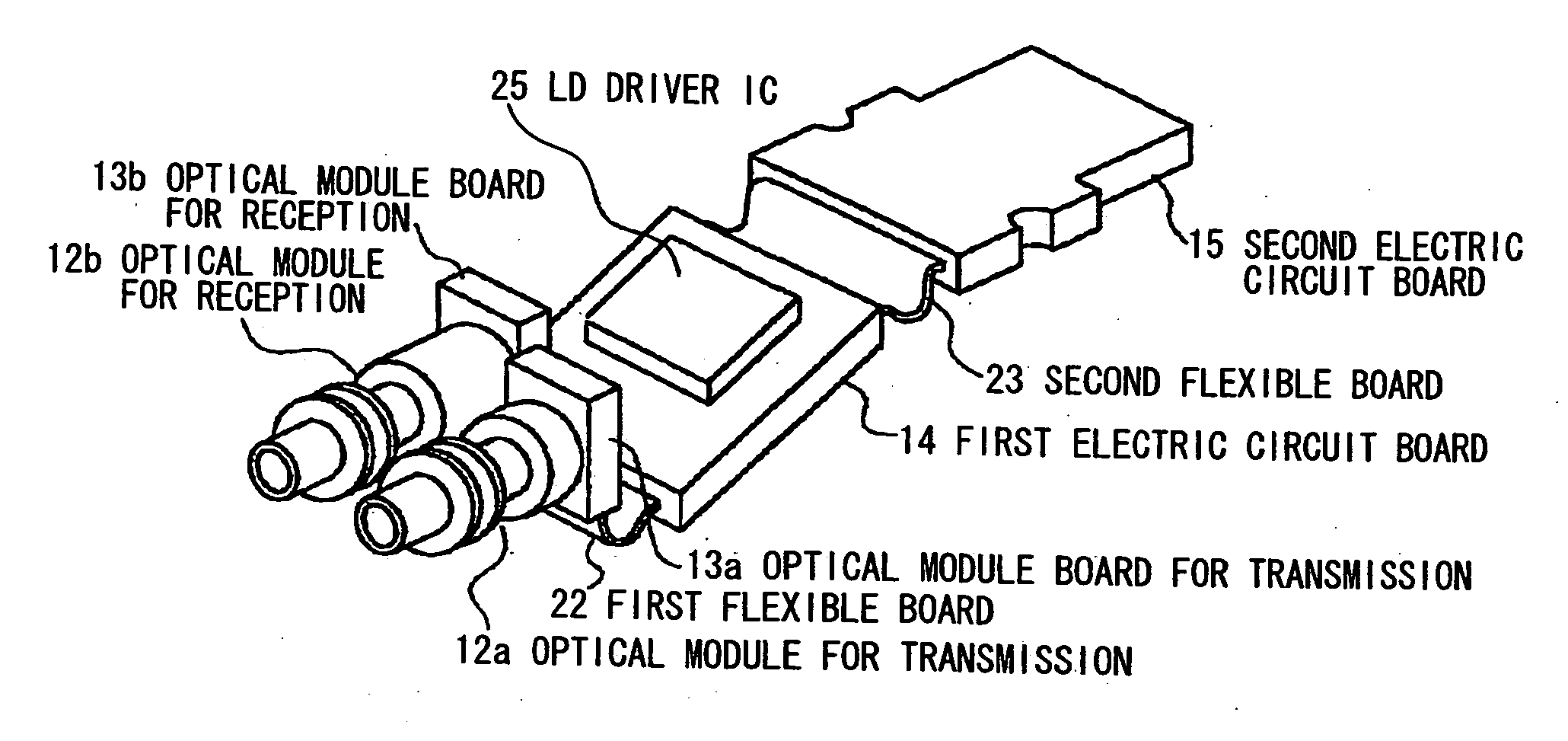
A board assembly, an optical transceiver using same, and a method for mounting a board assembly that can relax a stress occurred at a flexible board. A board assembly 1 comprises a flexible board 2, a first rigid board 3, and a second rigid board 4. The first rigid board 3 and the second rigid board 4 are connected with each other by means of the flexible board 2. Since the flexible board 2 is preformed before the attachment, the stress occurred at the flexible board 2 can be relaxed.

Description

[0001] The present application is based on Japanese Patent Application No. 2005-139631 filed on May 12, 2005, the entire contents of which are incorporated herein by reference. BACKGROUND OF THE INVENTION [0002] 1. Field of the Invention [0003] The present invention relates to fabrication of a structure (such as optical transceiver) in which both of rigid boards mounted on, for instance, different objects are connected with each other by a flexible board, and more particularly, to a board assembly, an optical transceiver using the same and a method for mounting the same on the objects. [0004] 2. Description of the Related Art [0005] An optical transceiver is used as an interface for connecting an optical transmission path and an electric communication device, which conducts an electrical processing of optical transmission signal of the optical transmission path. For achieving this purposes, the optical transceiver is provided with a built-in optical module and built-in electric circ...

Claims


Application Information

Patent Timeline
Patent Type & Authority Applications(United States)
IPC IPC(8): G02B6/36
CPCG02B6/4201G02B6/4246G02B6/4292H05K2201/2009H05K3/4691H05K2201/10121H05K1/189G02B6/4281G02B6/4283
Inventor ISHIGAMI, YOSHIAKIKOBAYASHI, NORIBUMITAKAHASHI, RYUTAHIRUTA, AKIHIROSUNAGA, YOSHINORI
Owner HITACHI CABLE
Learn More