Electron cyclotron resonance (ecr) plasma source having a linear plasma discharge opening

Inactive Publication Date: 2006-11-16
ROTH & RAU B V
View PDF8 Cites 4 Cited by
  • Summary
  • Abstract
  • Description
  • Claims
  • Application Information

AI Technical Summary

Benefits of technology

[0008] The ECR plasma source can be advantageously further developed such that in addition to the multi-pole magnetic arrangements in the area of the partial plasma discharge apertures one or a plurality of additional multi-pole magnetic arrangements are securely or movably arranged outside of the partial plasma chambers. Thus the plasma formation in the interior of the partial plasma chambers can be influenced in a specific manner.
[0015] The advantage of the inventive ECR plasma source is particularly comprised in that by overlaying at least two individual plasmas, a dense and largely homogeneous plasma can be generated with which it is possible to advantageously perform effective plasma treatment of large substrates or substrate arrangements.
[0016] While in the prior art, in the case of large linear plasmas, e.g. during layer deposition, the layer thicknesses have inhomogeneities that are greater than ±8%, with the inventive ECR plasma source it was possible to produce layer thicknesses of silicon nitride layers over a length of the plasma discharge of approx. 800 mm with inhomogeneities of less than ±2%.
[0017] Process control that is very flexible practically is possible by varying the wave power fed in, the shape of the partial plasma chambers, and the position and strength of the magnetic fields of the multi-pole magnetic field arrangement and of a variable gas supply.

Problems solved by technology

However, it is disadvantageous that the plasma density in the longitudinal axis of the gap-shaped aperture fluctuates relatively widely and, transverse to the longitudinal axis, has a parabola-shaped expansion with a relatively small apex radius of curvature.

Method used


Image

  • Electron cyclotron resonance (ecr) plasma source having a linear plasma discharge opening
  • Electron cyclotron resonance (ecr) plasma source having a linear plasma discharge opening
  • Electron cyclotron resonance (ecr) plasma source having a linear plasma discharge opening

Examples


exemplary embodiment i

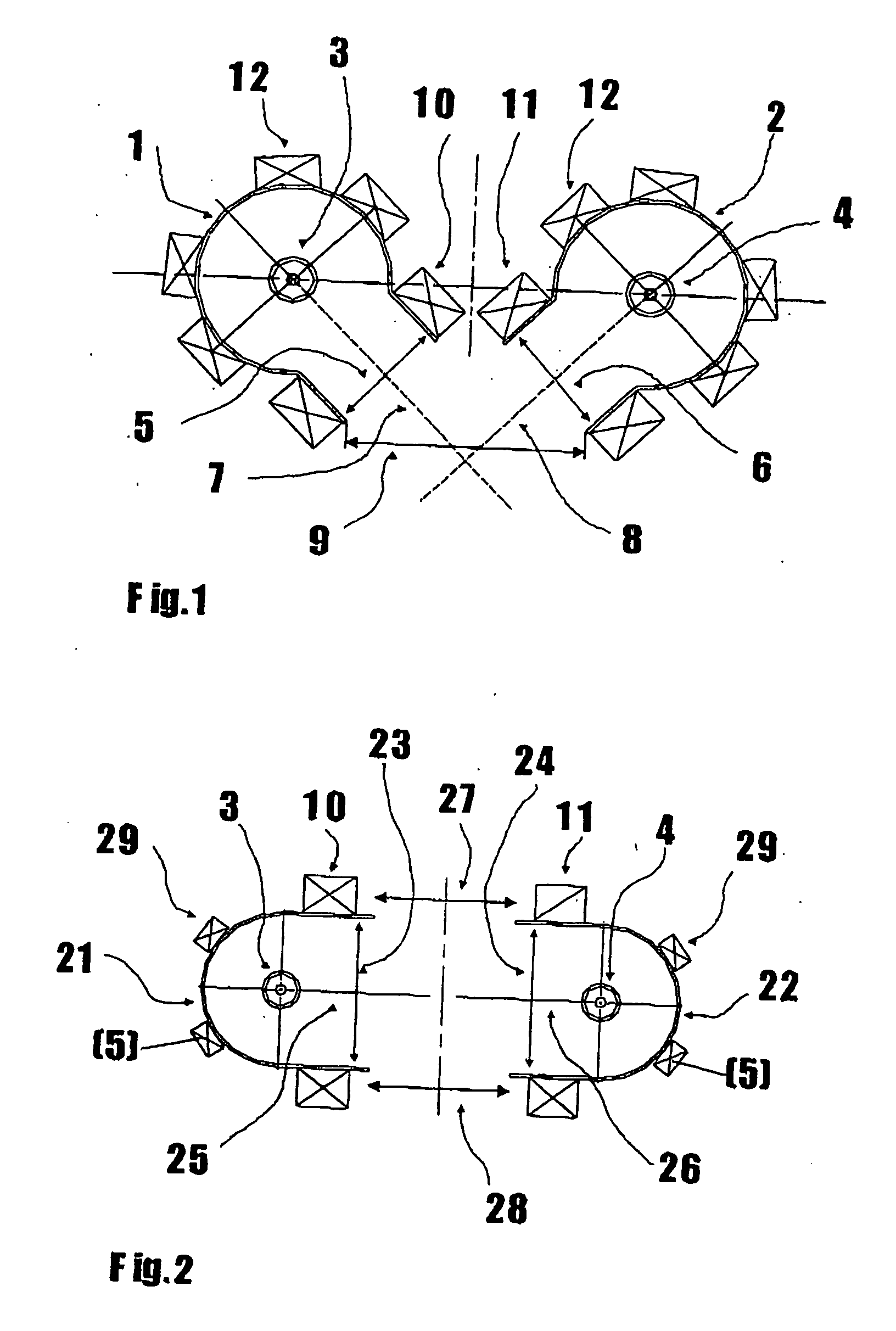
[0023] The inventive ECR plasma source in accordance with exemplary embodiment I largely comprises two individual ECR plasma sources. FIG. 1 depicts two partial plasma chambers 1 and 2 that together form the plasma chamber for the ECR plasma source and that are arranged in a vacuum chamber (not shown).

[0024] The partial plasma chambers 1 and 2 are embodied tube-shaped and are arranged in each of their interiors coaxial with an individual wave distributor 3, 4. The wave distributors 3, 4 correspond to known solutions and each comprise an internal conductor that can be connected to a device for generating microwaves preferably ranging between 910 MHz and 2.45 GHz. The wave distributors 3 and 4 are enclosed by protective tubes made of quartz glass. The interior space in the protective tubes can be rinsed with a gas and the wave distributors 3 and 4 can be cooled therewith.

[0025] The walls of the partial plasma chambers 1 and 2 act as external coaxial waveguides for the microwaves and...

exemplary embodiment ii

[0031] Belonging to exemplary embodiment II, FIG. 2 is a schematic depiction of an ECR plasma source having two plasma discharge apertures 27 and 28. The positions that are identical to those in exemplary embodiment I are labeled with the same position number in FIG. 2.

[0032] Each of two longitudinally extended U-shaped partial plasma chambers 21 and 22, each having one wave distributor 3, 4 that is arranged in the interior concentric with the curvature of the U-shaped partial plasma chambers 21, 22, has partial plasma discharge apertures 23, 24 in the width of the interior diameter. The radial lines 25 and 26 between each of the individual wave distributors 3 and 4 and the center of width of each partial plasma discharge apertures 23 and 24 are on one axis.

[0033] The distance between the partial plasma discharge apertures 23, 24 is selected such that formed at right angles and on both sides of the radial lines 25, 26 are two line-type plasma discharge apertures 27 and 28 that act...

exemplary embodiment iii

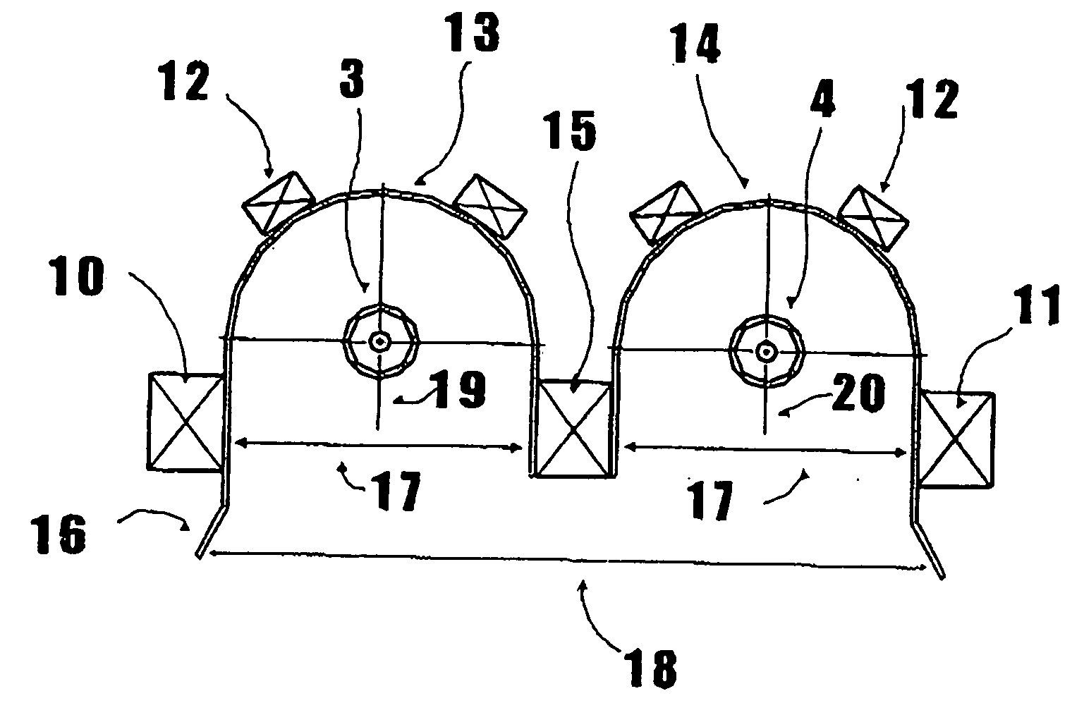
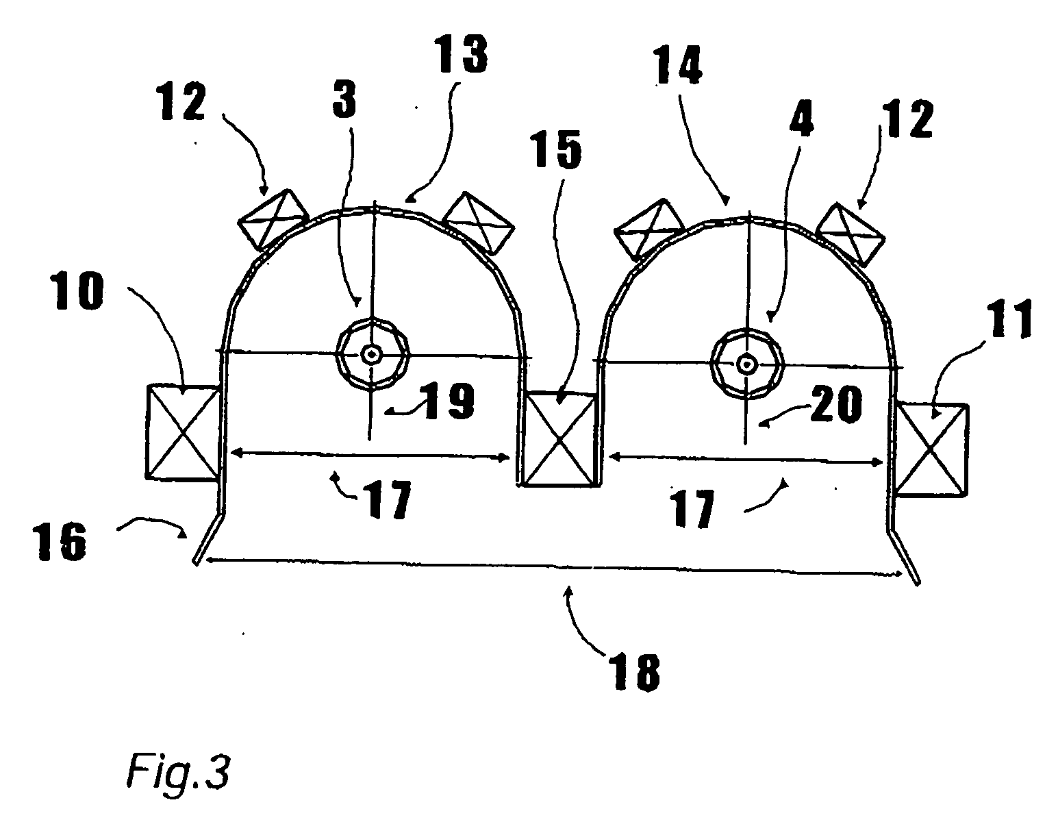
[0035] Belonging to exemplary embodiment III, FIG. 3 is a schematic depiction of an ECR plasma source having a plasma discharge aperture 18. The positions that are identical to those in exemplary embodiment I are labeled with the same position number in FIG. 3.

[0036] Each of two longitudinally extended U-shaped partial plasma chambers 13 and 14, each having one wave distributor 3, 4 that is arranged in the interior concentric with the curvature of the U-shaped partial plasma chambers 13, 14, has one partial plasma discharge aperture 17 in the width of the interior diameter. The radial lines 19 and 20 between each of the individual wave distributors 3 and 4 and the center of width of each partial plasma discharge aperture 17 are parallel to one another and form the plasma discharge aperture 18 of the ECR plasma source.

[0037] Each of the U-shaped partial plasma chambers 13, 14 has, on the exteriorly situated sides of the partial plasma discharge apertures 17, an outwardly angled ext...


PUM

PropertyMeasurementUnit
Angleaaaaaaaaaa
Magnetic fieldaaaaaaaaaa
Widthaaaaaaaaaa

Abstract

The invention relates to an electron cyclotron resonance (ECR) plasma source having a linear plasma discharge opening (9, 27, 28, 30), comprised of a plasma chamber, inside of which a centered wave distributor is provided, and having a multi-pole magnetic field arrangement in the area of the linear plasma discharge opening. The centered wave distributor consists of at least two separate wave distributors (3, 4) that are placed inside a respective partial plasma chamber (1, 2, 21, 22, 32, 23). A linear partial plasma discharge opening (7, 8, 23, 24, 34, 35) and multi-pole magnetic field arrangements (10, 11, 38, 39) are provided on each partial plasma chamber (1, 2, 21, 22, 32, 23). The at least two linear plasma discharge openings (7, 8, 23, 24, 34, 35) are arranged with regard to one another in such a manner that, together, they form at least one plasma discharge opening (9, 27, 28, 30) of the ECR plasma source.

Description

BACKGROUND OF THE INVENTION [0001] The invention relates to an ECR (electron cyclotron resonance) plasma source having a linear plasma discharge aperture on a plasma chamber that simultaneously acts as external conductor and in which a centric wave distributor is present that is connected to a device for generating a high frequency and to a multi-pole magnetic field arrangement in the area of the linear plasma discharge aperture. All technically acceptable and permitted frequency ranges can be considered for the high frequency. In practice frequencies between 13.56 MHz and 2.45 GHz have especially proved themselves. [0002] Numerous plasma generating devices are known from the prior art. DE 198 12 558 A1 describes an apparatus for generating linearly expanded ECR plasmas (Electron Cyclotron Resonance plasmas). An internal conductor is connected to a device for generating microwaves (910 MHz to 2.45 GHz) and is arranged coaxially in a well-conducting external coaxial waveguide that si...

Claims


Application Information

Patent Timeline
IPC IPC(8): C23C16/00H01J37/32H05H1/18
CPCH01J37/32192H05H1/18H01J37/32678H01J37/32541
Inventor MAI, JOACHIMROTH, DIETMAR
Owner ROTH & RAU B V
Why Eureka
Try Eureka