
Folding-up mechanism for an electric treadmill

Inactive Publication Date: 2006-11-09
WANG LEAO
View PDF5 Cites 8 Cited by
  • Summary
  • Abstract
  • Description
  • Claims
  • Application Information

AI Technical Summary

Benefits of technology

[0009] Thus, based on the above-mentioned considerations, the designer employs a flat lifting motor in cooperation with a drive screw, a slip pipe, an intermediate tube, a telescopic tube, a pull rod, a push rod, and a handrail frame to allow a platform frame to swivel on a pivotal point of an upright bar for adjusting the platform frame to an inclined and upright position with the handrail frame moved to a storage position. In this way, the lifting motor can complete the lifting action with less torque output so that the service life of the lifting motor can be extended. Moreover, the supporting force can be optimally controlled. This is the primary object of the invention.

Problems solved by technology

Although this prior art has its original design, the mechanism requires complicated and miscellaneous components.
In addition, the pull cable and the return springs are subject to fatigue and slack.
This is regarded as drawbacks of this prior art.
However, this apparatus doesn't have the function to bring the main frame in a tilt position.
Besides, the lifting motor applied its driving force to only one end of the main frame so that the arm of force is evidently mechanically too short.
So, the lifting motor is subject to overload that would cause damage to the lifting motor.
Also, this prior art doesn't have the function of tilting the main frame.

Method used


Image

  • Folding-up mechanism for an electric treadmill
  • Folding-up mechanism for an electric treadmill
  • Folding-up mechanism for an electric treadmill

Examples


Embodiment Construction

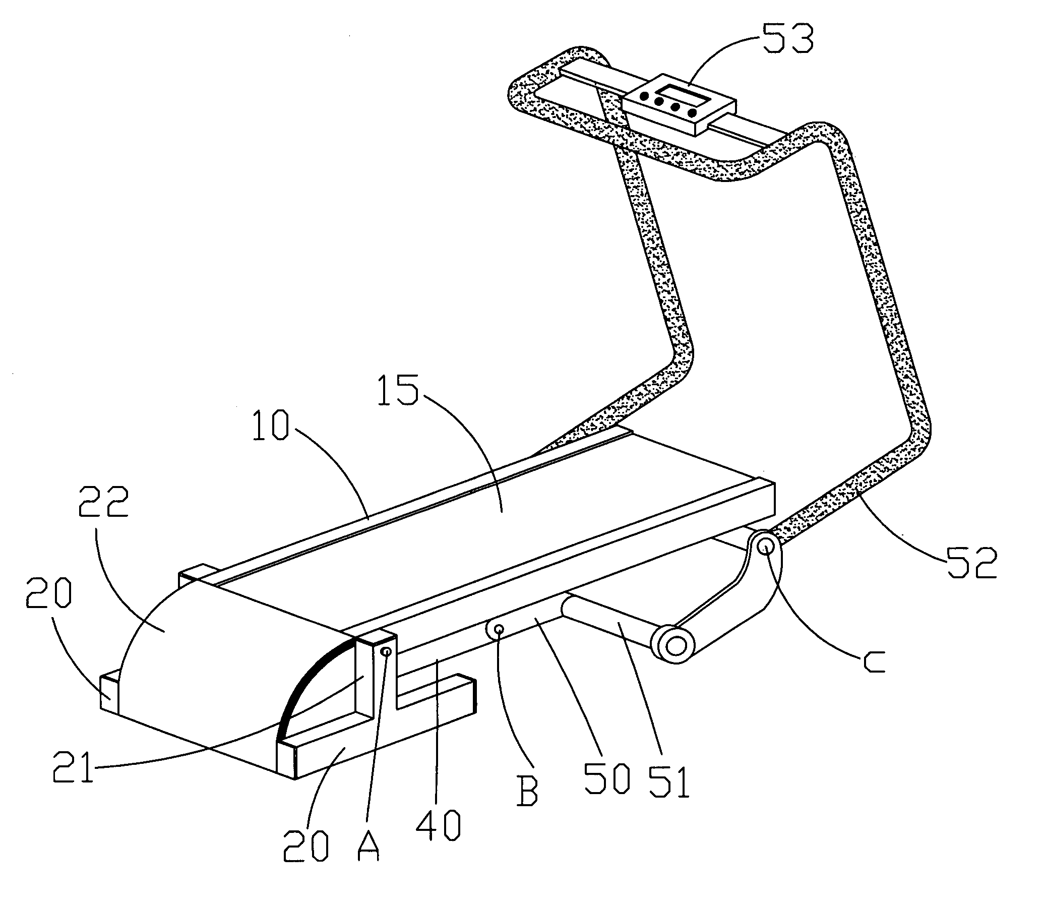
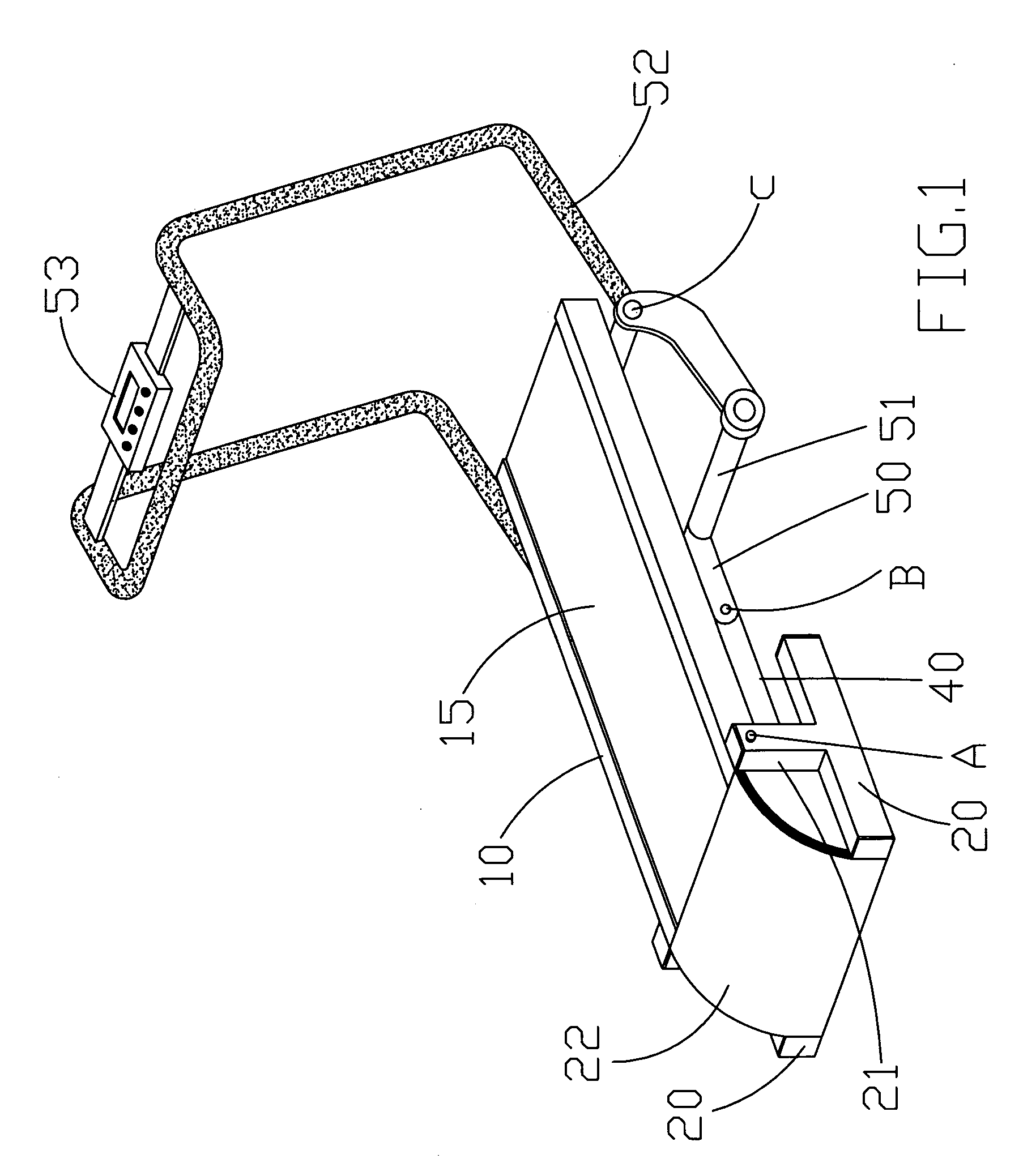
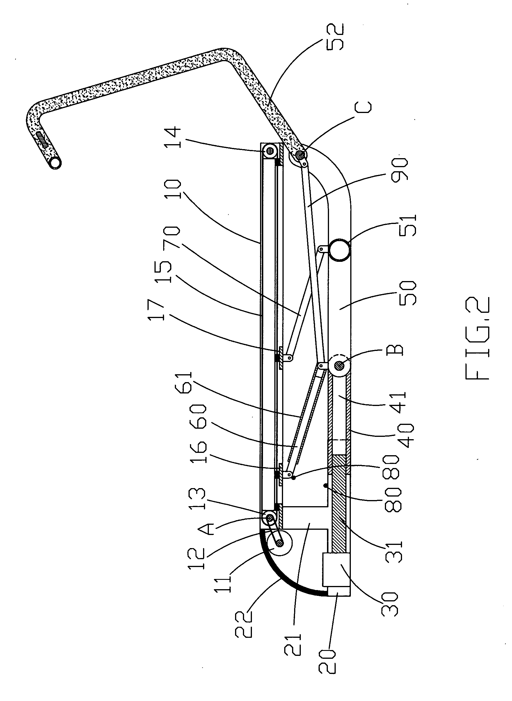
[0016] Referring to FIGS. 1 and 2, a treadmill in accordance with the invention includes:

[0017] a platform frame 10 having a rear roller 13 driven by a motor 11 through a driving belt 12, the rear roller 13 being active in cooperation with a front roller 14 for an in-place rotation of a continuous belt 15;

[0018] two base frames 20 having an upright bar 21 extending from a central point thereof, the platform frame 10 being pivotally connected to the upright bars 21;

[0019] a lifting motor 30 for driving a drive screw 31 to undergo an in-place rotation;

[0020] a slip pipe 40 having a female threaded hole 41 for receiving the drive screw 31;

[0021] an intermediate tube 50 pivotally disposed at a distal end of the slip pipe 40, a front crossbar 51 being connected at an opposing end of the intermediate tube 50, a handrail frame 52 extending upwardly from a rear end of the intermediate tube 50, an electronic console 53 being fitted atop the handrail frame 52;

[0022] a telescopic tube 60...


PUM


Abstract

A folding-up mechanism for an electric treadmill having a single lifting motor for adjusting a platform frame to an inclined and upright position with a handrail frame moved to a storage position. The lifting motor and a drive screw are interposed between two base frames. The drive screw is screwed in a slip pipe with female thread. An intermediate tube is pivotally coupled to a rear end of the slip pipe with a front crossbar and a handrail frame coupled to the opposing end of the intermediate tube. One end of the platform frame is pivotally attached to an upright bar of the base frames while a bottom side of the platform frame is pivotally coupled to a telescopic tube, a pull rod, and a push rod that are in turn coupled to the slip pipe, the intermediate tube, and the handrail frame so that the slip pipe is movable to and fro when the lifting motor is activated to impart an in-place rotation to the drive screw, thereby achieving the expected effects.

Description

[0001] This application is a continuation-in-part of U.S. patent application of Ser. No. 11 / 123,159 filed May 6, 2005.BACKGROUND OF THE INVENTION [0002] 1. Fields of the Invention [0003] The invention relates to a folding-up mechanism for an electric treadmill, and more particularly, to a folding-up mechanism having a single lifting motor for adjusting a platform frame to an inclined and upright position with a handrail frame moved to a storage position. [0004] 2. Description of the Related Art [0005] A tilting mechanism of a conventional treadmill is used to adjust the supported angle of a main frame relative to a base frame for creating a certain walking slope. Meanwhile, a fold-up mechanism is used to fold-up the main frame in a storage position for reducing the space occupied by the treadmill. Generally speaking, these can be classified into a manual and an automatic type. The present invention is an improvement of the above-mentioned mechanisms. [0006] U.S. Pat. No. 5,733,228 t...

Claims


Application Information

Patent Timeline
IPC IPC(8): A63B22/02
CPCA63B2210/56A63B22/0023A63B71/0622A63B21/0083A63B21/0087A63B22/0235F16B7/10A63B2071/0658A63B2220/801A63B2225/30A63B2210/50
Inventor WANG, LEAO
Owner WANG LEAO
Learn More