Magnet configuration with device for attenuation of voltage spikes of a power supply and method for operation thereof

a technology of power supply and configuration, which is applied in the direction of superconducting magnets/coils, measurement devices, instruments, etc., can solve the problem of relatively unimportant precise construction of power supply, and achieve the effect of maintaining the field stability of the superconducting magnet coil system and producing an excessive amount of hea

Inactive Publication Date: 2006-11-09
BRUKER BIOSPIN
View PDF25 Cites 10 Cited by
  • Summary
  • Abstract
  • Description
  • Claims
  • Application Information

AI Technical Summary

Benefits of technology

[0015] In a preferred embodiment of the inventive magnet configuration, at least two networks are connected between the connecting points of the current path and the power supply in such a manner that the connections of the first network, facing away from the power supply, are connected to the connections on the power supply side of the second network, wherein the second network comprises at least one inductance and the second network connections facing away from the power supply are connected to each other via at least one resistance, with the connections on the power supply side being connected to each other via at least the resistance and the inductance. The filtering effect can, in principle, be increased through use of an appropriate number of networks until the voltage fluctuations no longer disturb the measurements.
[0032] It is also advantageous to adjust a pulsed or time-varying power supply voltage in such a manner that its average voltage largely compensates for the drift caused by the resistance of the magnet system.

Problems solved by technology

The precise construction of the power supply is thereby relatively unimportant.

Method used


Image

  • Magnet configuration with device for attenuation of voltage spikes of a power supply and method for operation thereof
  • Magnet configuration with device for attenuation of voltage spikes of a power supply and method for operation thereof
  • Magnet configuration with device for attenuation of voltage spikes of a power supply and method for operation thereof

Examples


Embodiment Construction

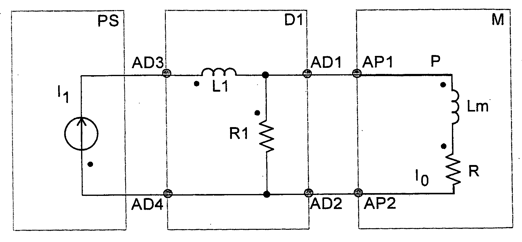
[0039]FIG. 1 schematically shows an inventive configuration, which comprises a superconducting magnet coil system M with a superconducting coil Lm, a power supply PS and an inventive network D1 for attenuating voltage spikes. The magnet coil system M has a resistance R that is shown as an equivalent resistance in the circuit diagram. The magnet coils system M is connected to a power supply PS via connecting points AP1, AP2 of a current path P and via the network D1. The power supply PS feeds current I1 to the magnet coil system M via the network D1. The network D1 is connected to the power supply PS via network D1 connections AD3, AD4.

[0040] The network D1 comprises an inductance L1 and a resistance R1. The connections AD1, AD2 of the network D1, facing away from the power supply PS, are connected to each other via the resistance R1, whereas the connections AD3, AD4 on the power supply side are connected to each other via the resistance R1 and the inductance L1. This inventive desi...


PUM

PropertyMeasurementUnit
voltageaaaaaaaaaa
magnetic frequencyaaaaaaaaaa

Abstract

A magnet configuration comprising a superconducting magnet coil system (M) which has a working volume and an ohmic resistance (R) of zero or more, and a current path (P) which comprises parts of the magnet coil system (M), with connecting points (AP1, AP2), a power supply (PS, PS′), and an electric network (D1, D1′, D2), wherein the connecting points (AP1, AP2) of the current path (P) are electrically connected to connections (AD1, AD2, AD1′, AD2′) of an electric network (D1, D1′, D2) facing away from the power supply, and the power supply (PS, PS′) is electrically connected to connections (AD3, AD4) on the power supply side of the electric network (D1), and wherein the network (D1, D1′) comprises a resistance (R1), is characterized in that the network (D1, D1′) comprises an inductance (L1), wherein the connections (AD1, AD2) are connected to each other via the resistance (R1), and the connections (AD3, AD4) are connected to each other via the resistance (R1) and the inductance (L1). This improves attenuation of the field fluctuations such that the voltage that is effectively applied across the magnet is sufficiently constant to prevent disturbance of high-resolution NMR and MRI methods.

Description

[0001] This application claims Paris Convention priority of DE 10 2005 020 690.5 filed May 03, 2005 the complete disclosure of which is hereby incorporated by reference. BACKGROUND OF THE INVENTION [0002] The invention concerns a magnet configuration comprising a superconducting magnet coil system having a working volume and an ohmic resistance of zero or more during operation, and having at least one current path which comprises at least parts of the magnet coil system, with connecting points, a power supply and at least one electric network, wherein the connecting points of the current path are electrically connected to connections of at least one electrical network, facing away from the power supply, and the power supply is electrically connected to connections of the electric network on the power supply side, and wherein the network comprises at least one resistance. [0003] A magnet configuration of this type is disclosed in US 2003 / 0057942 A1. [0004] Magnet configurations compr...

Claims


Application Information

Patent Timeline
Patent Type & Authority Applications(United States)
IPC IPC(8): H01F6/00
CPCG01R33/3815H01F6/008H01F6/005
Inventor SPREITER, ROLFSCHAUWECKER, ROBERT
Owner BRUKER BIOSPIN
Why Eureka
Try Eureka