Method of measuring sub-micrometer hysteresis loops of magnetic films
- Summary
- Abstract
- Description
- Claims
- Application Information
AI Technical Summary
Benefits of technology
Problems solved by technology
Method used
Image
Examples
embodiment 1
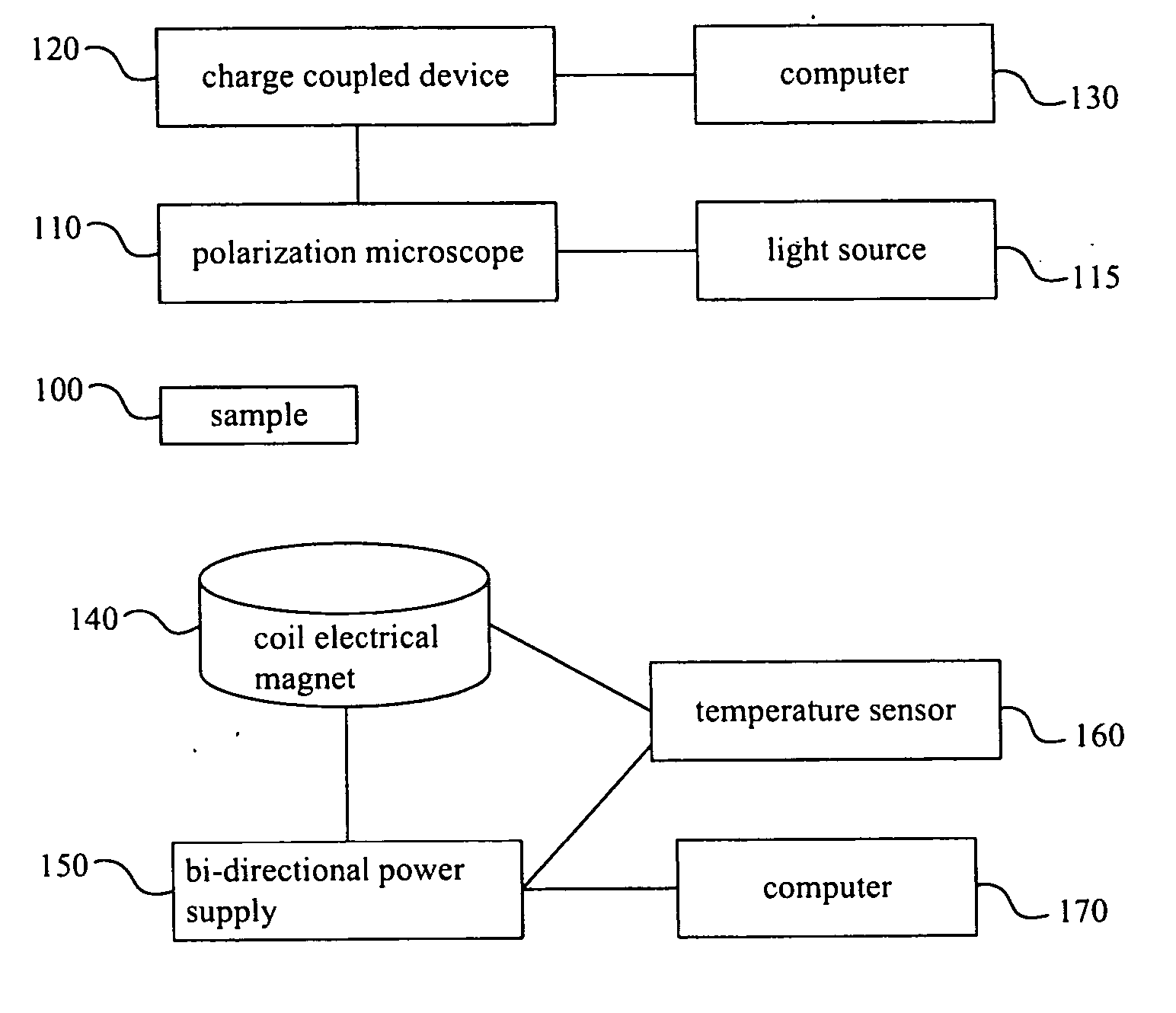
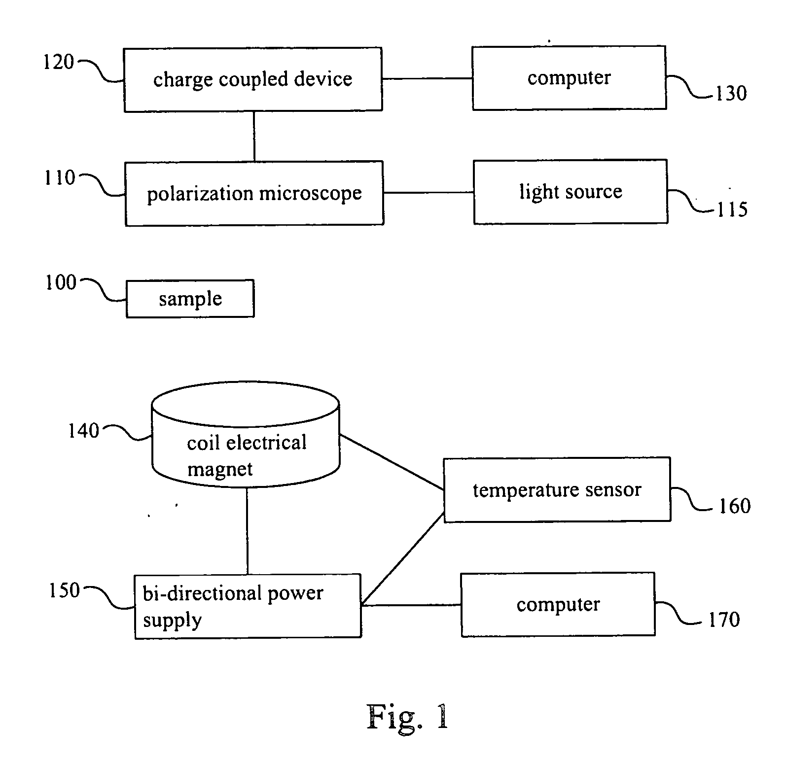
[0043] In this embodiment, a continuous magnetic film is used to illustrate the above measuring method and statistical result. The material of the continuous magnetic film to be measured is Tb18(Fe80Co20)82 and the size of the observation area is 33 μm×33 μm. The size of each pixel is 0.11 μm×0.11 μm. The scanned range of the magnetic field applied on the sample is from −2000 to +2000 Oe (Oersted). The grayscale number of the image detected by the CCD has 256 levels.
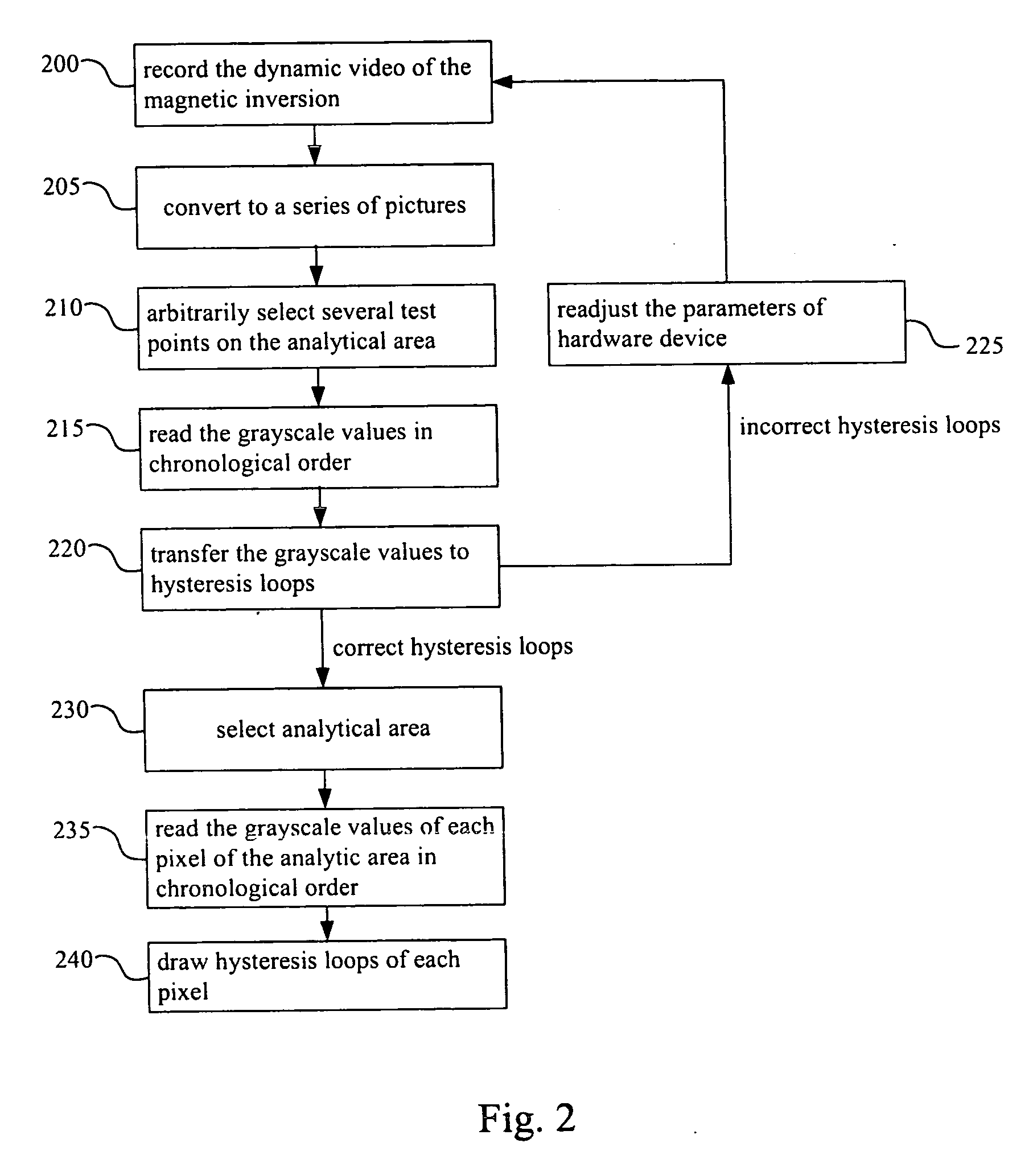
[0044]FIG. 4 shows the pictures which are converted from the dynamic video of magnetic moment inversion of the continuous magnetic film. The magnitudes of the applied magnetic fields are marked on right-up side of each picture in FIG. 4. In FIG. 4, the darkness of color in different region of the analytical area is different. This phenomenon indicates that although the magnitude of the applied magnetic field on the whole sample is the same, the direction of the microscopic magnetic moment in different region is differen...
embodiment 2
[0047] The influence of different magnetic-field increasing-gradient to the coercivity of the sample will be tested in embodiment 2. The sample and test parameters used here are the same as embodiment 1. The magnetic-field increasing-gradient can be 10 Oe every 0.1 sec, 0.2 sec, 0.5 sec or 1 sec.
[0048] Using the above method to do image processing, data-converting and statistical analysis, the average coercivity distribution with the magnetic-field increasing-gradient is indicated as FIG. 8. In FIG. 8, the smoother the increasing gradient of the magnetic field is, the smaller of the average coercivity is. Moreover, differential coercivity (Hc=(|HL|−|HR|) / 2) between left coercivity and right coercivity can also be calculated. FIG. 9 is the statistical distribution chart of the differential coercivity. The influence of different magnetic-field increasing-gradient to the differential coercivity can be seen in FIG. 9.
Image Data Processing of a Magnetic Film Having Array Patterns
[004...
embodiment 3
[0052] Here a patterned magnetic film having an array of holes of the same depth is used as an example to illustrate the above measuring method and the statistical result. The hole size of the patterned magnetic film is 2 μm×2 μm. The hole spacing is 2 μm and the hole depth is 13 nm. The material of the array patterned magnetic film is Dy20(Fe80Co20)80. The observed analytical area is 33 μm×33 μm. The pixel size is 0.11 μm×0.11 μm. The scan range of the applied magnetic field on the sample is −2000 to 2000 Oe. The grayscale number detected by the CCD is 256 levels.
[0053]FIG. 10 shows the pictures, which are converted from dynamic video of magnetic moment inversion of a patterned magnetic film. The magnitude of the applied magnetic field is marked on each picture of FIG. 10. All these pictures have not been image processed to reduce the edge noise produced by light diffraction at the hole edge. In the pictures of FIG. 10, the array pattern of the hole is blurry and the darkness vari...
PUM
 Abstract
Description
Claims
Application Information
 - R&D
- Intellectual Property
- Life Sciences
- Materials
- Tech Scout
- Unparalleled Data Quality
- Higher Quality Content
- 60% Fewer Hallucinations
Browse by: Latest US Patents, China's latest patents, Technical Efficacy Thesaurus, Application Domain, Technology Topic, Popular Technical Reports.
© 2025 PatSnap. All rights reserved.Legal|Privacy policy|Modern Slavery Act Transparency Statement|Sitemap|About US| Contact US: help@patsnap.com


