
Cardiac support cannula device and method

a cannula and support technology, applied in the field of cardiovascular surgery, can solve the problems of long and tedious open-heart valve repair or replacement surgery, high risk of complications, and surgeons' time-consuming, and achieve the effect of prolonging the tim

Inactive Publication Date: 2006-11-02
POKORNEY JAMES L
View PDF7 Cites 53 Cited by
  • Summary
  • Abstract
  • Description
  • Claims
  • Application Information

AI Technical Summary

Benefits of technology

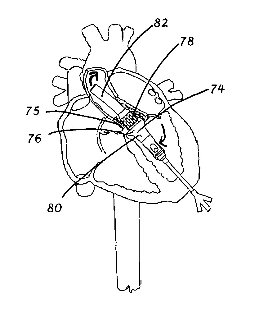
[0013] The primary object of the present invention is not focused on any specific therapeutic mechanisms or implants located near or on the outside surface of an apically inserted device, but instead, the primary object of the present invention is focused on the mechanisms and methods required to extend the time these therapies can be performed by providing a means for controlled one-way blood flow through the inside of the device while therapy is performed near or on the outside of the device.
[0018] Therapeutic mechanisms or implants can be located near or on the outside surface of

Problems solved by technology

Open-heart valve repair or replacement surgery is a long and tedious procedure and involves a gross thoracotomy, usually in the form of a median sternotomy.
Because the heart is not actively beating, the surgeon can spend a considerable amount of time ensuring that the valve is implanted into the correct position and is firmly secured to the heart wall.
This method, however, is highly invasive and often results in significant trauma, risk of complications, as well as extended hospitalization and painful recovery period for the patient.
It is known by those knowledgeable in the art that a significant source of complications can be attributed to the use of the external cardiopulmonary bypass blood circuit.
The use of a percutaneous approach, however, introduces new complexities compared to open-heart surgery.
One inherent difficulty in the minimally invasive percutaneous approach is the limited space that is available within the vasculature.
Consequently, the introduction of tools and prosthetic devices becomes a great deal more complicated.
A second inherent difficulty in the beating heart procedure is that the implant must be positioned and permanently affixed to the heart in a relatively short time period to ensure blood flow out of the heart is not significantly impeded.
Unfortunately, the apical installation methods known in the prior art also require a short implant time similar to percutaneous approaches.
Accordingly, while apical access heart valve surgery has the potential to produce beneficial results equal to or superior to open-chest methods or percutaneous methods, the requirement that the procedure needs to be done quickly because the valve implantation tools occlude heart outflow tract limits the procedure's potential for high quality clinical success.

Method used


Image

  • Cardiac support cannula device and method
  • Cardiac support cannula device and method
  • Cardiac support cannula device and method

Examples


Embodiment Construction

Structure

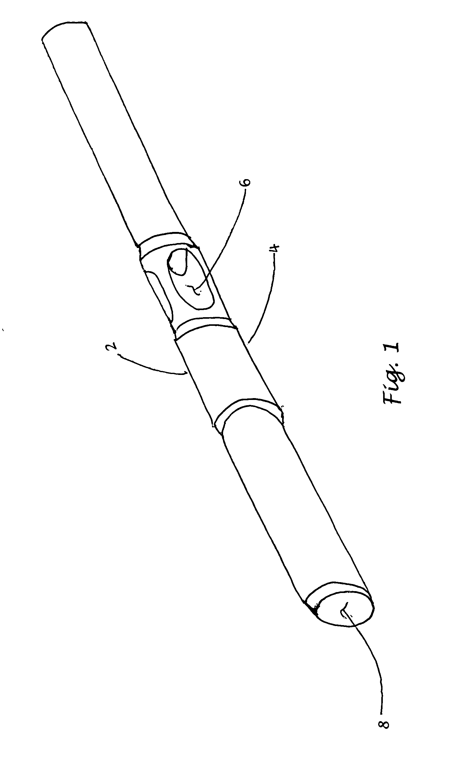
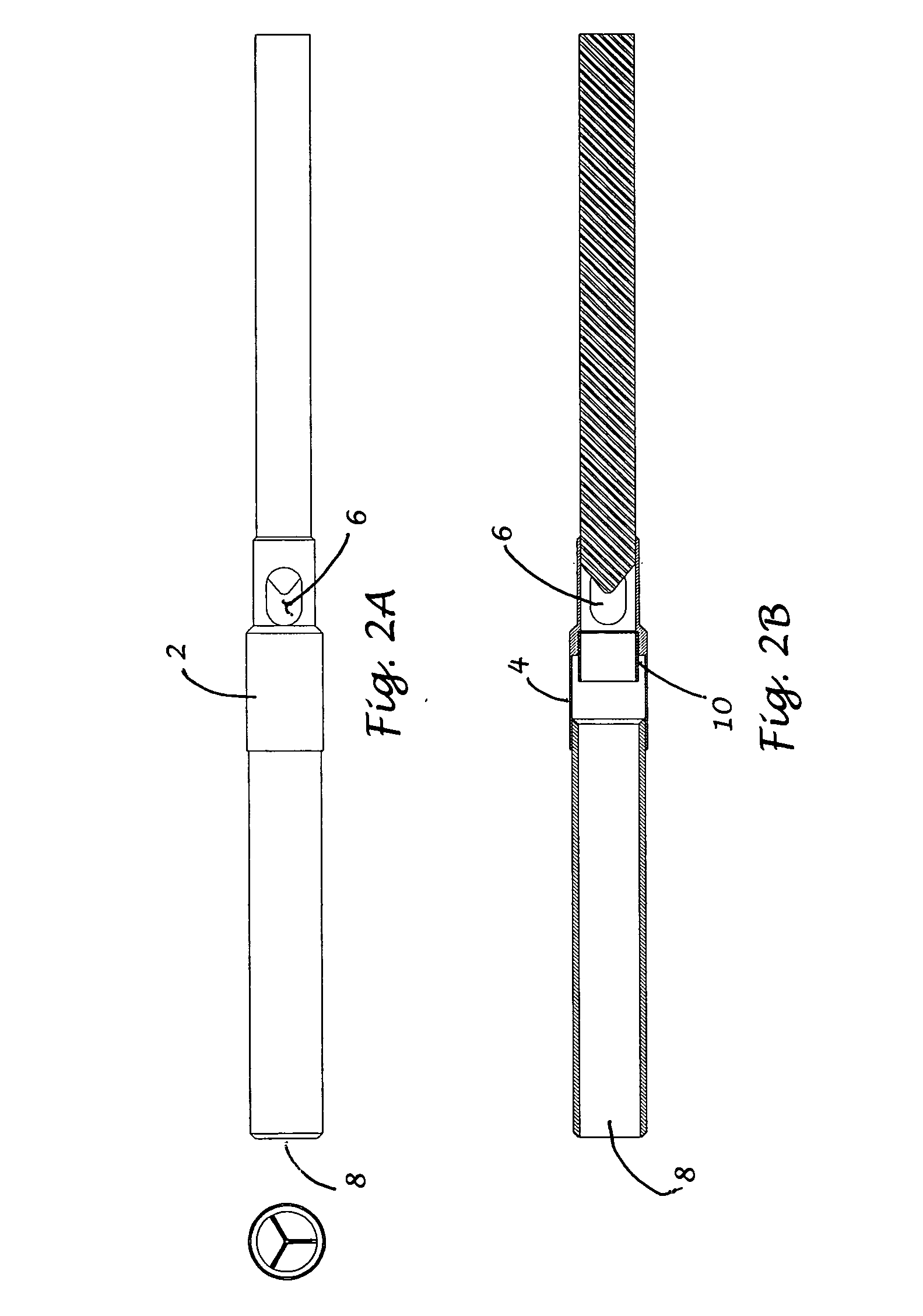
[0039] In a preferred embodiment as shown in FIGS. 3A-3C, the Cardiac Support Cannula 10 comprises three main elements: a Transfer Shaft 12, a Flow Housing 14, and an Outflow Cannula 16.

Transfer Shaft

[0040] The Transfer Shaft 12 is the most proximal element of the device. The purpose of the Transfer Shaft is to provide user control and orientation of the other, more distal elements of the device and to allow fluid communication with the more distal elements of the device or the heart itself.

[0041] The Transfer Shaft 12 comprises a Tubular Member 14 with a Port Connector 16 attached to the proximal end and a Flow Diverter 18 attached to the distal end.

[0042] The Port Connector 16 is composed of polycarbonate plastic or some other suitable biocompatible material. The Port Connector 16 has three proximal ports identified as the Annulus Balloon Port 18, the Infusion Port 20, and the Stent Balloon Port 21. These ports are in common communication with one Distal Port 24. The...


PUM


Abstract

This invention describes apical access methods and devices that enable repair, modification, removal, and / or replacement of a defective heart valve while allowing the beating heart to deliver blood flow through the defective valve annulus for an extended period of time in volumes sufficient to sustain life. The invention is comprised of a flow housing having a blood inflow opening, a blood outflow opening, and a one-way valve disposed within the flow housing between the inflow and outflow openings.

Description

[0001] This application claims priority from provisional patent application U.S. Ser. No. 60 / 645,177 filed 2005 Jan. 19.BACKGROUND [0002] 1. Field of Invention [0003] The present invention relates generally to methods and systems for cardiovascular surgery. More particularly, the invention relates to less invasive apical access methods and devices that repair, modify, remove, and / or replace a defective heart valve while simultaneously allow the heart to continue delivering blood flow through the defective valve annulus sufficient to sustain life. [0004] 2. Clinical Need [0005] Various surgical techniques may be used to repair a diseased or damaged heart valve, such as annuloplasty (contracting the valve annulus), quadrangular resection (narrowing the valve leaflets), commissurotomy (cutting the valve commissures to separate the valve leaflets), or decalcification of valve and annulus tissue. Alternatively, the diseased heart valve may be replaced or pushed aside by a prosthetic valv...

Claims


Application Information

Patent Timeline
IPC IPC(8): A61F2/24
CPCA61B17/3207A61B17/3421A61B2017/00243A61F2250/0059A61B2017/22097A61B2017/22098A61F2/24A61B2017/22014
Inventor POKORNEY, JAMES L.
Owner POKORNEY JAMES L
Learn More