
RF microwave connector for telecommunication

Inactive Publication Date: 2006-11-02
INSERT ENTERPRISE
View PDF4 Cites 5 Cited by
  • Summary
  • Abstract
  • Description
  • Claims
  • Application Information

AI Technical Summary

Benefits of technology

[0014] For improving the combination structure of a male terminal of a receptacle of a coaxial microwave connector and inner wires of a coaxial cable, allowing the manufacturing more convenient and cheap and enabling the ratio of bad product rate to be lowered down, the present invention is proposed.
[0016] Another object of the present invention is to provide a RF microwave connector for telecommunication, enabling a male terminal of a receptacle to be combined with inner wires of a coaxial cable tightly and not to loose so as to enhance the good product rate.

Problems solved by technology

The receptacle mentioned above is a structure welded to a circuit board; it is objected to the limitation that it must be fixed on the circuit in practical application, a set of connectors with a same length of wire are not allowed to use in variety of circuit boards with different specifications or circuit arrangements.
The manufacturing way welding the coaxial cable and the female terminal manually mentioned above cannot be replaced with an automatic machine manufacturing way; it is labor and time wasting.

Method used


Image

  • RF microwave connector for telecommunication
  • RF microwave connector for telecommunication
  • RF microwave connector for telecommunication

Examples


Embodiment Construction

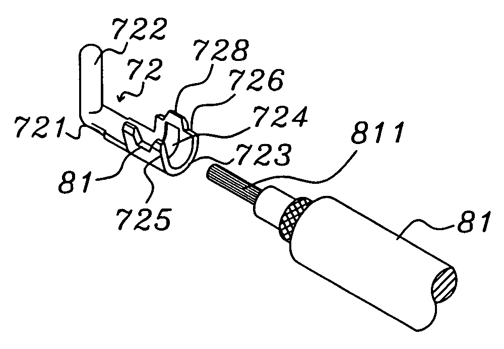
[0035] Please refer to FIG. 11A to 11C. A male terminal 71 of a first preferred embodiment according to the present invention has a main body 711. A raised portion 712 is extended from one end of the main body 711 used for combining with a female terminal. An arc-shaped clamping section 713 is disposed at another end of the main body 711 and a groove hole 714 is disposed in the arc face of the clamping section 713. Two edges 715 and 716 of the clamping section 713 are symmetrically arched.

[0036] The design that the two edges 715 and 716 of the clamping section 713 of the male terminal 71 are symmetrically arched in the preferred embodiment is suitable for using only a simpler and cheaper manufacturing machine, the edges 715 and 716 can be bended face to face smoothly to clamp inner wires 811 of a coaxial cable 81 stably. A part of the inner wires 811 corresponding to the groove hole 714 will be deformed by a force and sunk into the groove hole 714 during the inner wires 811 is clam...


PUM


Abstract

A RF microwave connector for telecommunication comprises a receptacle; a metal housing of the receptacle is combined with an insulator; a male terminal is combined with the hollow portion of the insulator; the male terminal has a main body, a raised portion is extended from one end of the main body for inserting a female terminal; an arc-shaped clamping section is disposed at another end of the main body, two edges of the clamping section are symmetrically arched so as to allow the edges of the clamping section to be bended oppositely smoothly to clamp inner wires of a coaxial cable stably when that the clamping section is combined with the inner wires is processed.

Description

BACKGROUND OF THE INVENTION [0001] 1. Field of the Invention [0002] The present invention relates to an electric connector, and more particularly to a receptacle of a RF microwave connector for telecommunication. [0003] 2. Description of Related Art [0004] Please refer to FIG. 1. A tin soldered micro-mini-connector available in the market comprises a receptacle 10 and plug 20. The bottom 10 of the receptacle 10 is soldered onto a circuit board of a notebook computer, personal digital assistant (PDA) or cellular phone. And, the plug 20 can be inserted in the receptacle 10 and another end thereof is connected to an antenna of a device such as a cellular phone through a signal line so as to make contact with signals. The receptacle 10 has a metal housing 11 and the lower end thereof is connected to an insulator 12. The insulator 12 is extended in the housing 11 and the central part thereof is formed with a raised portion 121. A male terminal 13 is combined in the raised portion 121. A ...

Claims


Application Information

Patent Timeline
IPC IPC(8): H01R9/05
CPCH01R9/0518H01R4/184
Inventor WANG, SHUN-PING
Owner INSERT ENTERPRISE
Learn More