
Phase estimation for coherent optical detection

a phase estimation and optical detection technology, applied in electromagnetic transmission, electrical equipment, transmission, etc., can solve the problems of difficult implementation, increased bit error rate, and errors in received digital data

Inactive Publication Date: 2006-11-02
TAYLOR MICHAEL GEORGE
View PDF3 Cites 65 Cited by
  • Summary
  • Abstract
  • Description
  • Claims
  • Application Information

AI Technical Summary

Benefits of technology

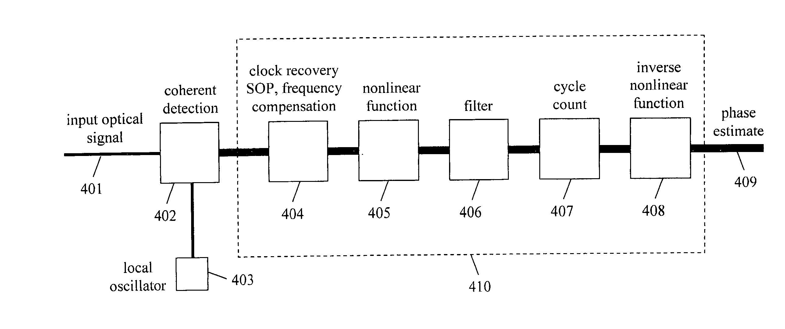
[0034] The digital signal processor in the optical coherent detection apparatus forms a sequence of complex values corresponding to the electric field of the symbols before a phase estimate is applied. The method of making a phase estimate has the following stages. First, a nonlinear function is applied to the sequence of electric field values to remove the averaging effect of the transmitted data. Then a digital filter is applied, whose transfer function is a Wiener filter. The feedback and feedforward taps of the filter are chosen using a look-ahead computation, so that the filter has the correct Wiener filter transfer function, but it can be implemented without feedback of recent results. The Wiener filter is the optimal linear estimate of the phase. Two kinds of Wiener filter may be used, zero-lag or finite-lag filters. Next a cycle count operation is performed. The cycle count function is derived using a look-ahead computation, so that it can be implemented without feedback of recent results. The nonlinear function is then reversed to give a sequence of complex values whose phases are the final phase estimate. The reversal of the nonlinear function is performed taking into account the cycle count. This means that there are few cycle slips. After applying the phase factor to the original sequence of electric field values, a decision is made on the digital value of each symbol. Differential logical detection may be subsequently applied to remove the impact of any remaining cycle slips. This may be followed by decoding of any forward error correction code on the transmitted data. The FEC code may be chosen to correct short bursts of errors, so that the differential logical detection operation does not lead to excess bit errors.

Problems solved by technology

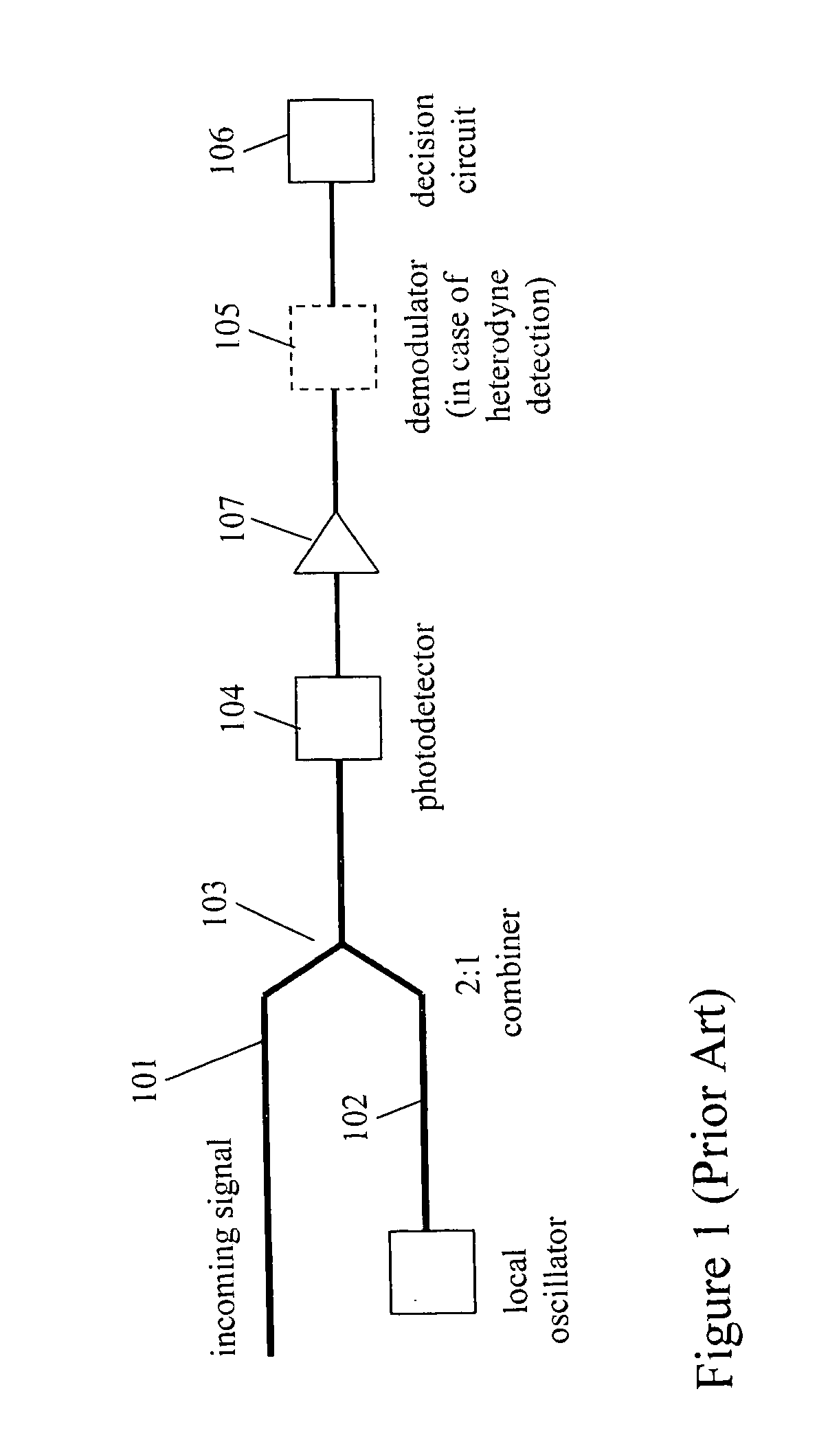
Typically homodyne detection gives better performance than heterodyne detection, but is harder to implement because of the need for optical phase locking.
Conversely, any inaccuracy in the estimates {circumflex over (ω)} and {circumflex over (φ)}(t) leads to errors in the received digital data.
However, it is important to make an estimate close to the optimal estimate for a reference parameter that changes rapidly on the time scale of the symbol period, otherwise there will be a substantial increase in the bit error rate.
However, the optical phase of the signal compared to the local oscillator may vary rapidly and randomly, unless expensive narrow linewidth lasers are used.
However there is no application in radio with the same level of phase noise as with optical coherent detection.
There are no examples in the prior art having such a high τsΔv, and the methods used in radio cannot be applied to optical coherent detection.
So the techniques used in these optical coherent detection experiments do not provide a solution for implementing optical coherent detection using digital signal processing with inexpensive wide linewidth lasers.
However, this filter shape is not close to the optimal filter shape, which increases the bit error rate.
Differential logical detection is used after decisions are made to avoid the impact of cycle slips, but it has the disadvantage that it increases the bit error rate.
Another disadvantage is that every time the filter complex output crosses the negative real boundary (every time a cycle count occurs) an extra symbol error is inserted, which leads to a background bit error rate even when the transmission system additive noise is low.

Method used


Image

  • Phase estimation for coherent optical detection
  • Phase estimation for coherent optical detection
  • Phase estimation for coherent optical detection

Examples


Embodiment Construction

[0044] The present invention is a phase estimation method that can be implemented in a parallel digital signal processor architecture, and which does not use feedback from recent results. There are many modulation formats used to transmit digital information on subcarriers. The methods used to estimate the phase may differ in the details, but have a common basic approach, as is discussed in “Digital communication receivers: synchronization, channel estimation & signal processing” by H. Meyr et al. and “Synchronization techniques for digital receivers” by U. Mengali & A. N. D'Andrea. The method to estimate the phase of an Mary PSK signal will be described below. It will be apparent to those skilled in the art that the present invention for making phase estimates may be utilized for other modulation formats, such as offset QPSK or QAM.

[0045]FIG. 4 illustrates the phase estimation process in the preferred embodiment of the present invention. The optical signal 401 is input to a sample...


PUM


Abstract

The present invention is a method and apparatus to make an estimate of the phase of a signal relative to the local oscillator in an optical coherent detection subsystem that employs a digital signal processor having a parallel architecture. The phase estimation method comprises operations that do not use feedback of recent results. The method includes a cycle count function so that the phase estimate leads to few cycle slips. The phase estimate of the present invention is approximately the same as the optimal phase estimate.

Description

RELATED APPLICATIONS [0001] This utility application claims the benefit of U.S. Provisional Patent Application Ser. No. 60 / 676631 by Michael G. Taylor, filed Apr. 29, 2005, and is hereby incorporated by reference.BACKGROUND OF THE INVENTION [0002] 1. Field of the Invention [0003] This invention relates to optical data transmission over optical fibers. Specifically, and not by way of limitation, the present invention relates a method and system providing an estimate of the phase of an optical signal during coherent detection. [0004] 2. Description of the Related Art A. Optical Fiber Communications [0005] Information has been transmitted over optical fibers for some time. Details about this field are disclosed in “Optical Communication Systems,” by J. Gowar (Prentice Hall, 2nd ed., 1993) and “Fiber-optic communication systems” by G. P. Agrawal (Wiley, 2nd ed., 1997), which are herein incorporated by reference. The information is usually in the form of binary digital signals, i.e. log...

Claims


Application Information

Patent Timeline
Patent Type & Authority Applications(United States)
IPC IPC(8): H04B10/06
CPCH04B10/60H04B10/63H04B10/6165
Inventor TAYLOR, MICHAEL GEORGE
Owner TAYLOR MICHAEL GEORGE
Learn More