
Desulfurization system with novel sorbent transfer mechanism

a transfer mechanism and desulfurization system technology, applied in the direction of filtration separation, combustible gas purification/modification, separation process, etc., can solve the problems of large hydrogen consumption cost, high sulfur content in such automotive fuels, and reduce the octane number, so as to reduce the octane loss and hydrogen consumption. , the effect of enhancing sulfur removal

Inactive Publication Date: 2006-11-02
CHINA PETROCHEMICAL CORP
View PDF15 Cites 12 Cited by
  • Summary
  • Abstract
  • Description
  • Claims
  • Application Information

AI Technical Summary

Benefits of technology

[0009] Accordingly, it is an object of the present invention to provide a novel hydrocarbon desulfurization system which employs a fluidized bed reactor and provides for continuous regeneration of the solid sorbent particulates.

Problems solved by technology

High levels of sulfurs in such automotive fuels is undesirable because oxides of sulfur present in automotive exhaust may irreversibly poison noble metal catalysts employed in automobile catalytic converters.
However, most conventional sulfur removal processes, such as hydrodesulfurization, tend to saturate olefins and aromatics in the cracked-gasoline and thereby reduce its octane number (both research and motor octane number).
In removing sulfur from diesel fuel by hydrodesulfurization, the cetane is improved but there is a large cost in hydrogen consumption.
The different pressures and atmospheres in the reactor and regenerator present a variety of challenges when continuously withdrawing and regenerating sulfur-loaded sorbent particulates from the reactor.
For example, the pressure differential between the reactor and regenerator can make it difficult to maintain the proper pressures in the reactor and regenerator while continuously transferring sulfur-loaded solid particulates from the reactor to the regenerator.
Such isolation of the hydrocarbon environment in the reactor from the oxygen environment in the regenerator can be difficult to maintain during continuous transfer of sulfur-loaded sorbent particulates from the reactor to the regenerator.

Method used


Image

  • Desulfurization system with novel sorbent transfer mechanism
  • Desulfurization system with novel sorbent transfer mechanism
  • Desulfurization system with novel sorbent transfer mechanism

Examples


Embodiment Construction

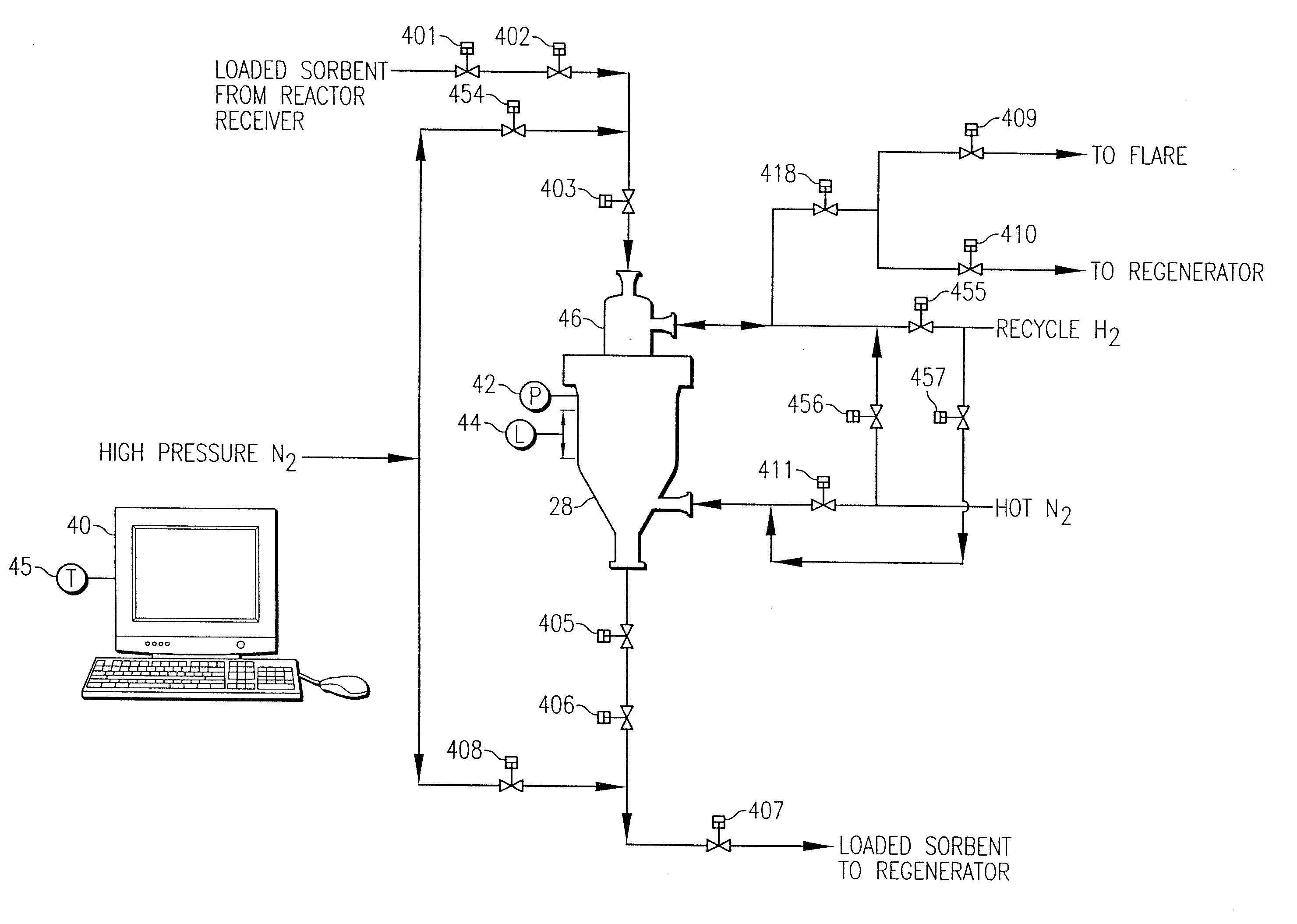
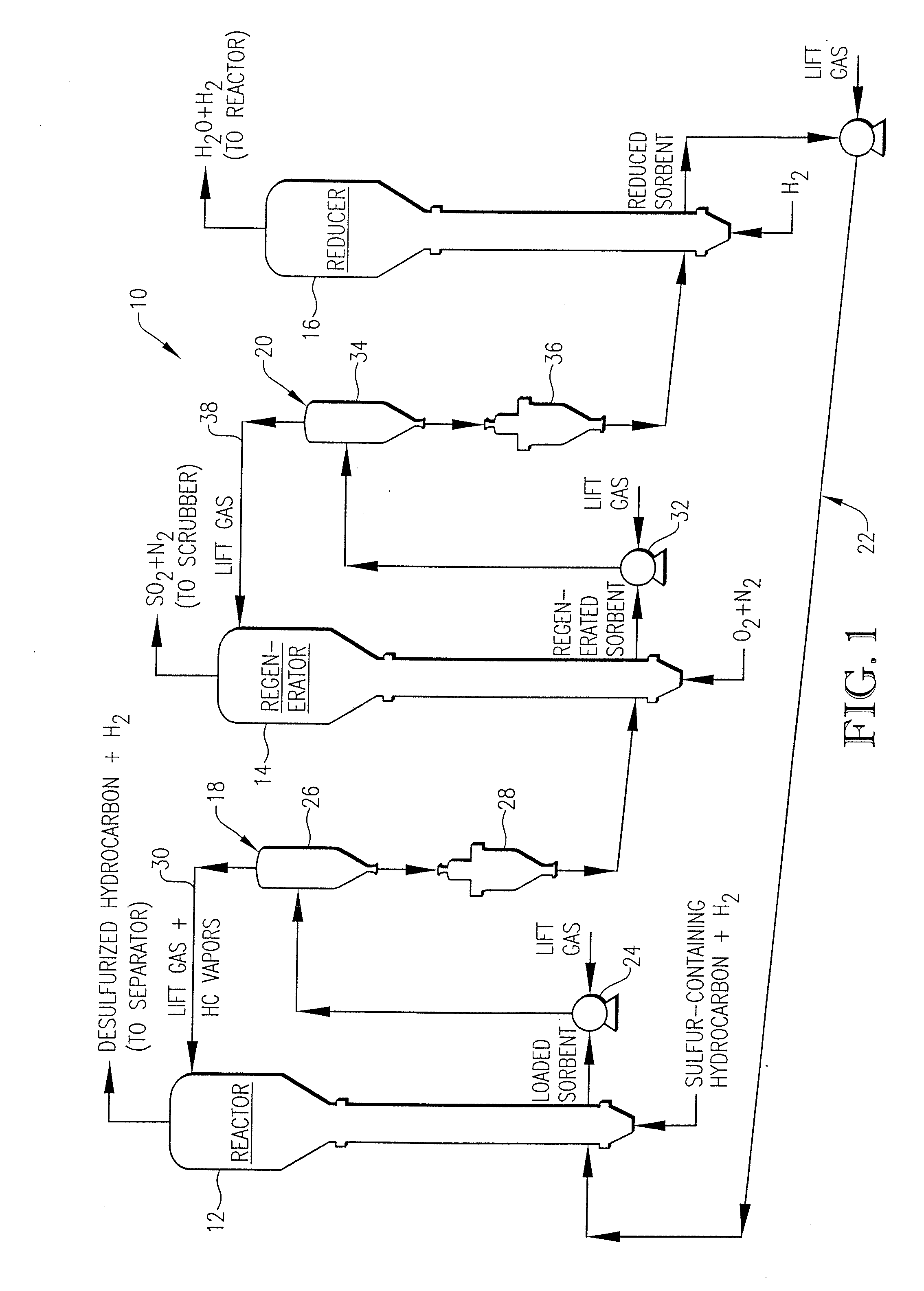
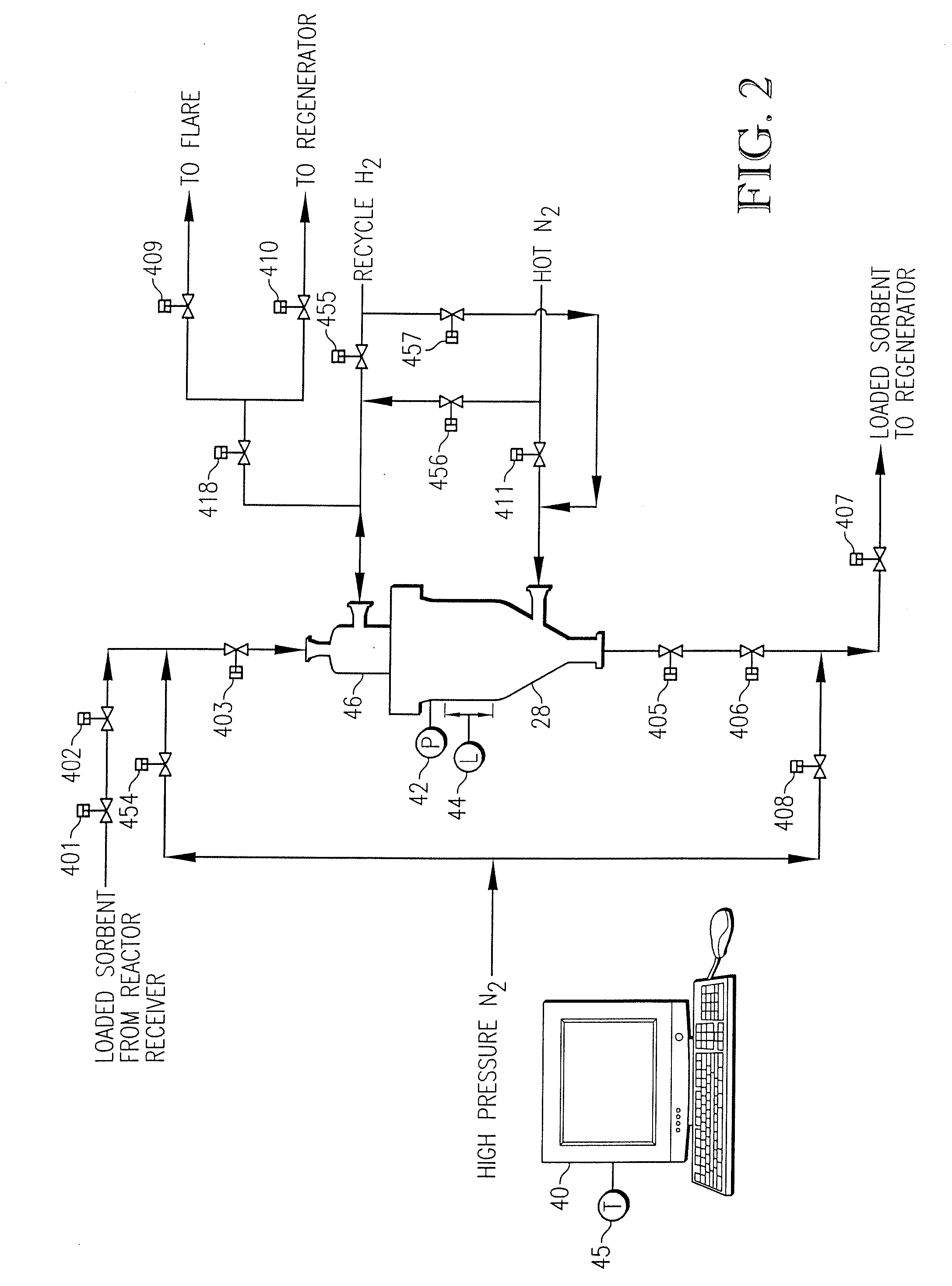
[0023] Referring initially to FIG. 1, a desulfurization unit 10 is illustrated as generally comprising a fluidized bed reactor 12, a fluidized bed regenerator 14, and a fluidized bed reducer 16. Solid sorbent particulates are circulated in desulfurization unit 10 to provide for continuous sulfur removal from a sulfur-containing hydrocarbon, such as cracked-gasoline or diesel fuel. The solid sorbent particulates employed in desulfurization unit 10 can be any sufficiently fluidizable, circulatable, and regenerable zinc oxide-based composition having sufficient desulfurization activity and sufficient attrition resistance. A description of such a sorbent composition is provided in U.S. patent application Ser. No. 09 / 580,611 and U.S. Patent application Ser. No. 10 / 072,209, the entire disclosures of which are incorporated herein by reference.

[0024] In fluidized bed reactor 12, a hydrocarbon-containing fluid stream is passed upwardly through a bed of reduced solid sorbent particulates. Th...


PUM

PropertyMeasurementUnit
Fractionaaaaaaaaaa
Pressureaaaaaaaaaa
Pressureaaaaaaaaaa

Abstract

A hydrocarbon desulfurization system employing regenerable solid sorbent particulates in a fluidized bed desulfurization reactor. The sulfur-loaded sorbent particulates are continuously withdrawn from the reactor and transferred to a regenerator. A novel solids transport mechanism provides for the safe and effective transfer of the sulfur-loaded sorbent particulates from the high pressure hydrocarbon environment of the reactor to the low pressure oxygen environment of the regenerator.

Description

RELATED APPLICATIONS [0001] This application is a continuation of U.S. patent application Ser. No. 10 / 120,700, filed Apr. 11, 2002, which is hereby incorporated by reference herein.BACKGROUND OF THE INVENTION [0002] This invention relates to a method and apparatus for removing sulfur from hydrocarbon-containing fluid streams. In another aspect, the invention concerns an improved system for transferring solid sorbent particulates between vessels in a hydrocarbon desulfurization unit. [0003] Hydrocarbon-containing fluids such as gasoline and diesel fuels typically contain a quantity of sulfur. High levels of sulfurs in such automotive fuels is undesirable because oxides of sulfur present in automotive exhaust may irreversibly poison noble metal catalysts employed in automobile catalytic converters. Emissions from such poisoned catalytic converters may contain high levels of non-combusted hydrocarbons, oxides of nitrogen, and / or carbon monoxide, which, when catalyzed by sunlight, form ...

Claims


Application Information

Patent Timeline
IPC IPC(8): C10G45/00B01D53/06B01J20/34C10G25/09C10G25/12C10G45/02
CPCB01D53/047B01J2220/56B01D53/12B01D2253/1122B01D2253/1124B01D2253/304B01D2256/24B01D2257/304B01D2257/306B01D2257/308B01D2259/40009B01D2259/40056B01D2259/40086B01D2259/403C10G25/09C10G25/12C10G45/02B01J20/06B01J20/08B01J20/3433B01J20/3458B01J20/0225B01J20/106B01D53/08
Inventor THOMPSON, MAX W.JAZAYERI, BEHZADZAPATA, ROBERTHERNANDEZ, MANUEL
Owner CHINA PETROCHEMICAL CORP
Learn More