
Handwheel-operated device

a technology of handwheel and chuck, which is applied in the direction of portable power-driven tools, applications, kitchen equipment, etc., can solve the problems of limited speed and/or torque that can be developed at the chuck, devices are therefore unsuitable for long-term use, and users who lack physical strength, and achieve the effect of accurate response of the speed of rotation

Inactive Publication Date: 2006-11-02
CAMBRIDGE CONSULTANTS LTD
View PDF21 Cites 45 Cited by
  • Summary
  • Abstract
  • Description
  • Claims
  • Application Information

AI Technical Summary

Benefits of technology

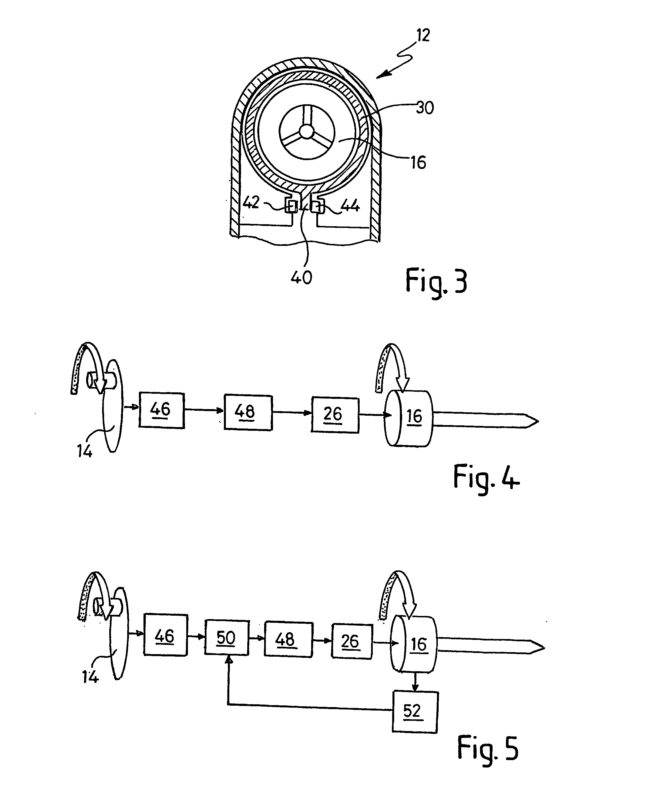
[0010] The first control means is more preferably operable to modulate the voltage applied to the first motor in dependence upon the angular velocity of the handwheel such that the angular velocity of the chuck is non-linearly related to the angular velocity of the handwheel, the ratio of handwheel speed to chuck speed decreasing with increasing handwheel speed. An increase in handwheel speed causes a greater than proportionate increase in chuck speed, and this type of first control means therefore enables a user to obtain very precise control of the angular displacement of the chuck at low speeds of rotation of the handwheel, yet also to obtain high angular velocities of the chuck that would otherwise require speeds of rotation of the handwheel that would be difficult or impossible for the user to achieve or sustain.
[0044] Where the device includes both the first further manual control and the first switch means, the first control means may advantageously be operable to cause the first motor to rotate the chuck only when the handle is in the extended position and the first further manual control is moved to the “on” position. If the first further manual control includes biasing means operable to urge it into the “off” position, it may function as a “dead man's handle” such that if a user of the device drops the device in use, the first further manual control moves to the “off” position, in which position rotation of the handwheel does not cause rotation of the chuck.

Problems solved by technology

However, the magnitude of the speed and / or torque that can be developed at the chuck is limited by the magnitude of the speed and / or torque applied to the handwheel, which must be provided by the user.
Such devices are therefore unsuitable for use over long periods or by users who lack physical strength, or if high levels of both speed and torque are required.

Method used


Image

  • Handwheel-operated device
  • Handwheel-operated device
  • Handwheel-operated device

Examples


Embodiment Construction

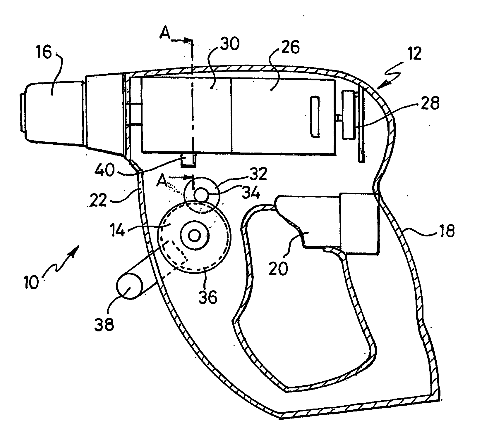
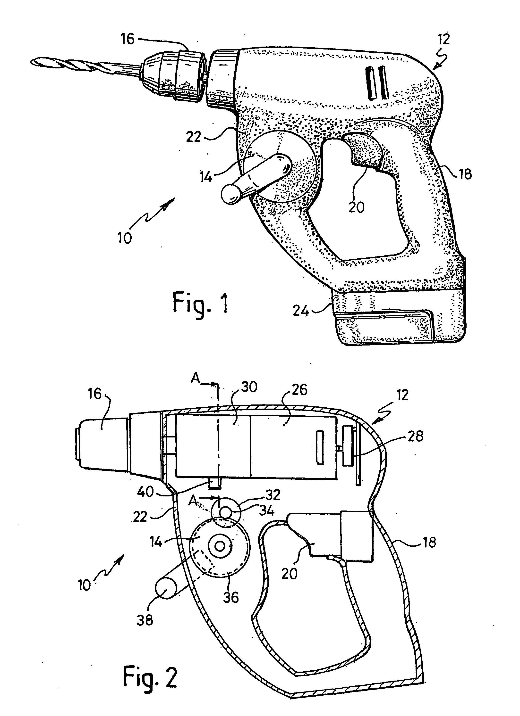
[0079] The cordless drill 10 of FIG. 1 comprises a body 12, a handwheel 14 and a chuck 16. Except for the handwheel, the drill 10 superficially resembles a conventional drill, with a pistol grip 18, trigger switch 20 located in the pistol grip, and forward housing portion 22 located in front of the trigger. The handwheel 14 is attached to the portion 22. A rechargeable battery 24 is removably attached to the base of the body.

[0080] Turning to FIG. 2, from which the battery 24 has been omitted for the purpose of clarity, the body 12 contains a first motor 26, a first rotary encoder 28, a gearbox 30, a second motor 32, a second rotary encoder (not shown), and first and second gear wheels 34 and 36, respectively. The body 12 further contains first control means in the form of a programmed microprocessor (not shown). The first rotary encoder 28 is made up of a multipole magnet and three Hall effect detectors and is attached to a first end of the spindle of the first motor 26. The gearb...


PUM

PropertyMeasurementUnit
Angleaaaaaaaaaa
Speedaaaaaaaaaa
Electric potential / voltageaaaaaaaaaa

Abstract

A handwheel-operated device comprising a body, a handwheel and a chuck, the handwheel and the chuck being rotatable relative to the body, and the device further comprising a first motor operable to rotate the chuck, first sensor means responsive to rotation of the handwheel and first control means operable in conjunction with the first sensor means to cause the first motor to rotate the chuck in dependence upon an angular displacement and / or angular velocity of the handwheel.

Description

FIELD OF THE INVENTION [0001] This invention relates to a handwheel-operated device and to a method of controlling a motor of a handwheel-operated device by sensing rotation of the handwheel and causing the motor to rotate a chuck in dependence upon the rotation of the handwheel. BACKGROUND TO THE INVENTION [0002] Mechanical devices of the kind having a handwheel connected to a chuck through a gear train, so that rotation of the handwheel causes a corresponding rotation of the chuck are well known. Hand drills and hand whisks are examples of such devices. These handwheel-operated devices are popular because a handwheel affords a high degree of control over the speed of rotation of the chuck. However, the magnitude of the speed and / or torque that can be developed at the chuck is limited by the magnitude of the speed and / or torque applied to the handwheel, which must be provided by the user. Such devices are therefore unsuitable for use over long periods or by users who lack physical ...

Claims


Application Information

Patent Timeline
IPC IPC(8): E21B17/22A47J43/10B23B45/02B25F5/00
CPCA47J43/1037B25F5/00B23B2260/128B23B45/02
Inventor WEBSTER, CRAIG DUNCAN
Owner CAMBRIDGE CONSULTANTS LTD
Learn More