Controlled leakage valve for piston cooling nozzle

Inactive Publication Date: 2006-11-02
BONTAZ CENT
View PDF7 Cites 20 Cited by
  • Summary
  • Abstract
  • Description
  • Claims
  • Application Information

AI Technical Summary

Benefits of technology

[0012] The problem put forward by the present invention is to design detachable and interchangeable means which, without modification or alteration of the engine block, efficiently make it possible to reduce these wear effects, and at the same time to reduce these parasitic noises and vibrations in engines outfitted with valve-type feed devices.
[0014] Such a structure can still provide a low flow rate of fluid in the cooling nozzles when the engine is turning at low revolutions, so as to lubricate the sliding contacts between the pistons and the liners. The leakage is calibrated so that the oil flow rate at low engine revolutions is just enough to enable the lubrication of the sliding contacts, but not to reduce the lubrication of the other moving parts of the engine in a substantial manner.
[0016] In this way, one minimizes the effects of wear by ensuring a permanent and well distributed lubrication of the moving parts of the engine, including when it is turning at low revolutions, that is, when the pressure of the cooling fluid is less than the particular threshold pressure. The direction of the jet is unchanged, and remains longitudinal against the piston top, regardless of the condition of the valve. The lubrication thus produced is optimal, since it is not perturbed by the movements of the piston.
[0018] At the same time, the maintaining of a slight oil circulation in the downstream channel when the pressure of the cooling fluid is less than the particular threshold pressure makes it possible to reduce the difference between the pressure in the upstream channel and the pressure in the downstream channel at the opening of the valve of the feed device. One thus dampens the movement of the blocking element of the valve of the feed device, thereby reducing in significant fashion the noise produced by the displacement of the blocking element of the valve.
[0023] One thus achieves a means of leakage in economical, simple and rapid manner, one that is easily dimensionable by the depth of the notch made.

Problems solved by technology

Likewise, in the known valve-type cooling nozzles, noise and vibrations perceptible to the human ear are produced upon opening of the valve of the feed devices for the cooling nozzles, which constitutes a parasitic noise source for the user.
As a result, its efficiency is not optimal.
The making of the secondary channel requires an additional machining of the engine block, which machining is costly and no modifiable, nor is it easily adaptable to all existing engine block configurations.

Method used


Image

  • Controlled leakage valve for piston cooling nozzle
  • Controlled leakage valve for piston cooling nozzle
  • Controlled leakage valve for piston cooling nozzle

Examples


first embodiment

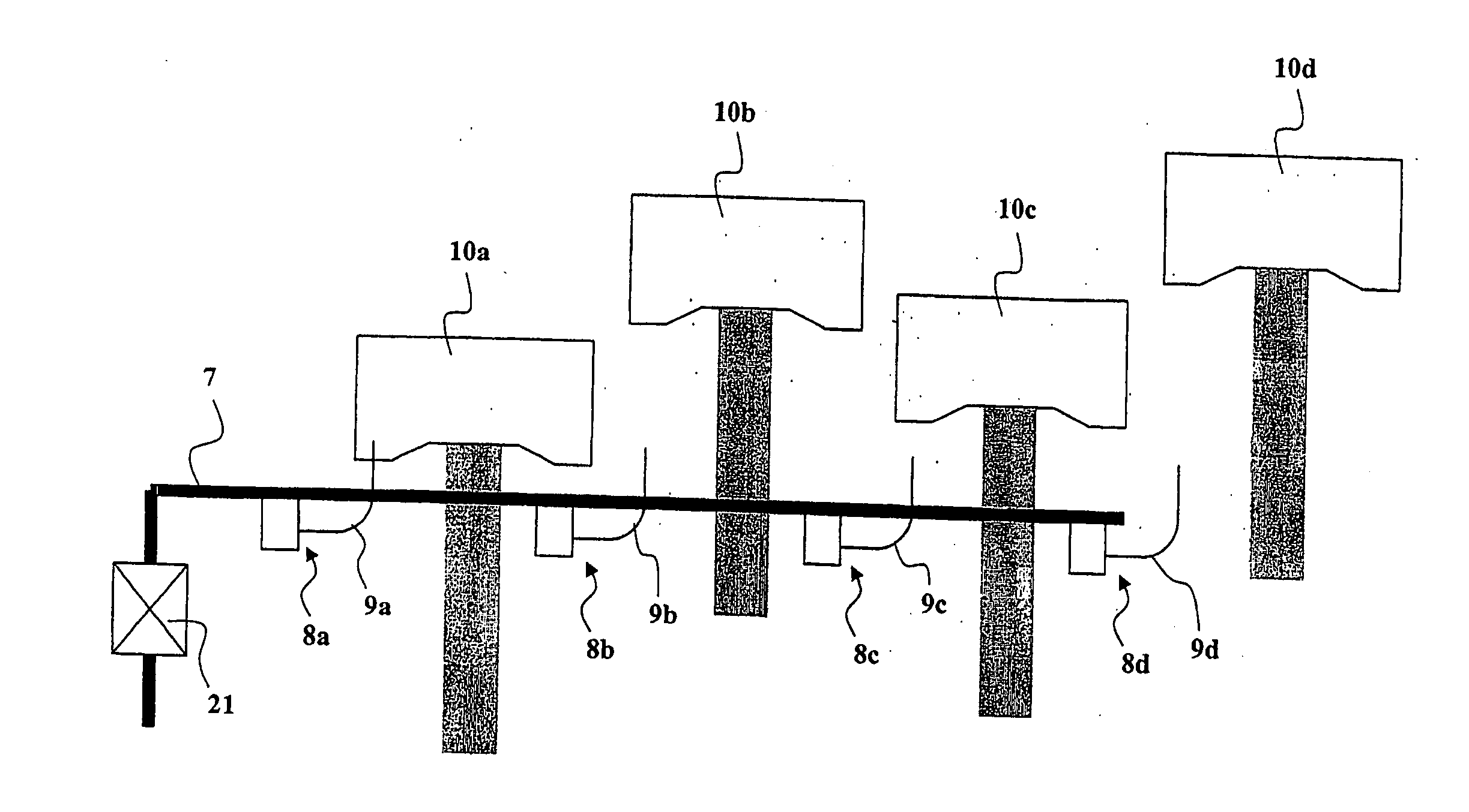
[0065]FIG. 1 shows a first embodiment according to the invention of a cooling and lubricating oil feed device for the pistons of an internal combustion engine. One shows here an oil feed device for the cooling nozzles of a four-cylinder in-line engine, but it goes without saying that the invention can be adapted without difficulty to any other engine having a different configuration (V-shaped, star-shaped, W-shaped, etc.) and a different number of cylinders.

[0066] In this arrangement, a central detachable valve 21 with calibrated leakage controls the flow of cooling and lubricating fluid from a feed channel 7 in the engine block to the detachable cooling and lubricating nozzles 8a, 8b, 8c and 8d which, by means of their respective downstream channels 9a, 9b, 9c and 9d direct a jet of cooling and lubricating fluid onto the top of the respective pistons 10a, 10b, 10c and 10d to be cooled.

[0067] In this arrangement, the detachable cooling and lubricating nozzles 8a, 8b, 8c and 8d do n...

second embodiment

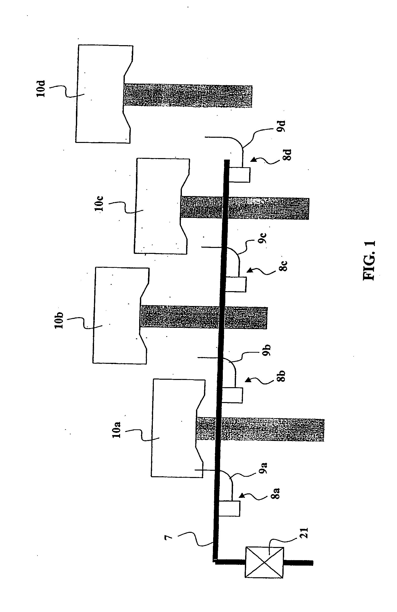
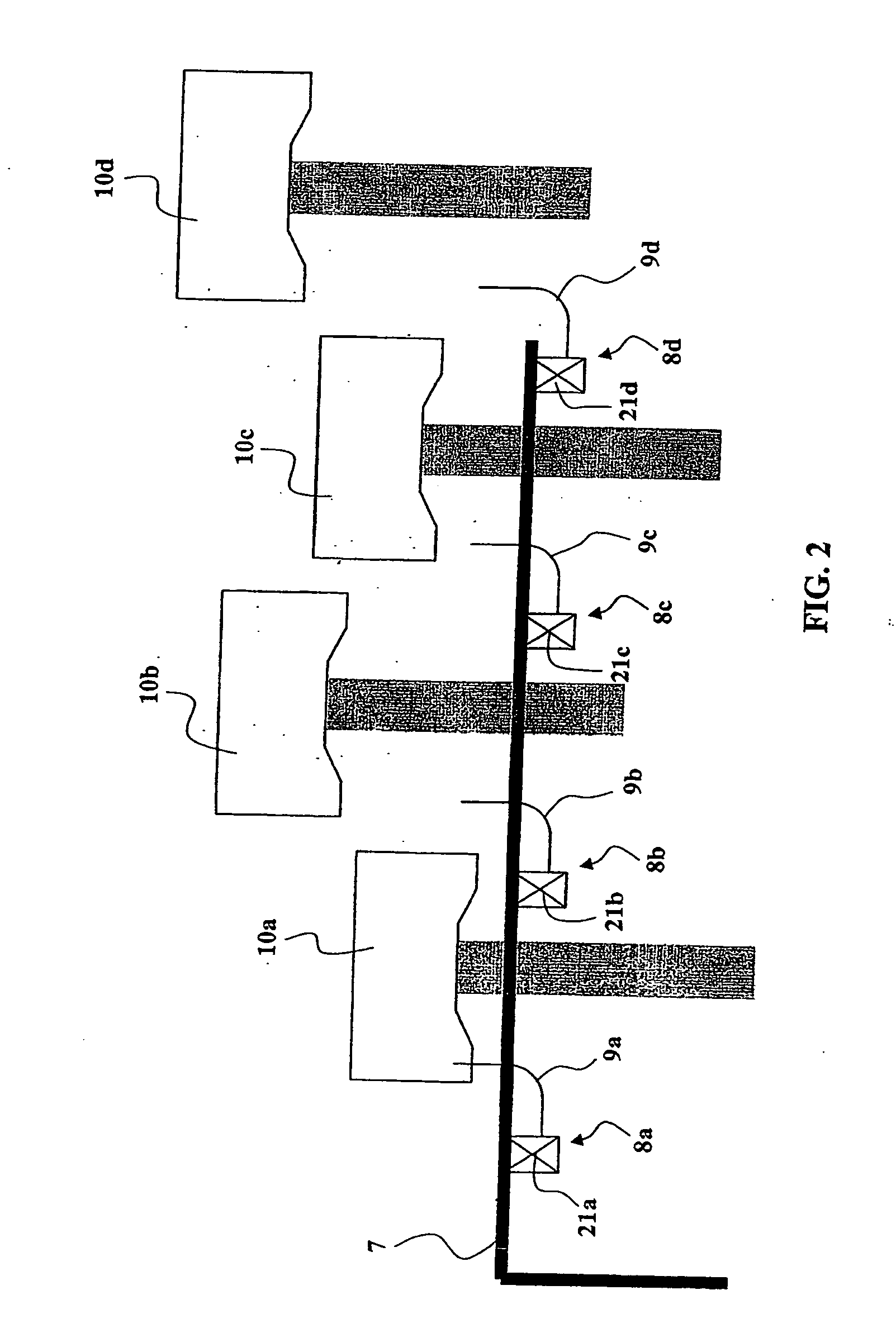
[0070]FIG. 2 shows a schematic view of the oil feed device for the cooling and lubricating nozzles 8a, 8b, 8c and 8d of pistons 10a, 10b, 10c and 10d according to the invention. In this embodiment, the cooling and lubricating fluid is supplied by the feed channel 7 to the nozzles 8a, 8b, 8c and 8d, each nozzle 8a, 8b, 8c and 8d itself comprising a valve 21a, 21b, 21c and 21d with a means of calibrated leakage.

[0071] Such valve nozzles 8a, 8b, 8c and 8d, comprising a valve 21a-21d and a means of calibrated leakage, are shown in FIG. 4, where one notices a double valve nozzle 110 with valve 21 of calibrated leakage means and two curved outlet tubes 11b, 11c. One also finds a single valve nozzle 120 combined with a valve 21 of calibrated leakage means and having one curved outlet tube 12b.

[0072] Such valve nozzles 110 or 120 have a valve body 210, whose upstream segment 21e is designed to fit axially into a bore of the engine along an axial direction of penetration. The valve nozzle i...

third embodiment

[0080]FIGS. 7a and 7b show a valve mechanism according to the invention, respectively in its closed state and in its open state.

[0081]FIG. 7a shows in cross section a valve according to the third embodiment of the invention in its closed state. The upstream channel 13 communicates with the feed channel 7 of the cooling circuit, in which a pressure prevails that is lower than the particular threshold pressure, chosen by the engine designer. A spring 15 pushes on the blocking element 16, which is a piston able to move in the compartment 17, to block the opening 18 of the seat 19, thereby preventing the passage of the cooling and lubricating fluid from the upstream channel 13 to the compartment 17 and the downstream channel 14.

[0082] There are two notches 20 made in the seat 19, constituting a means of leakage for the cooling and lubricating fluid arriving by the upstream channel 13 in the compartment 17, in parallel with the zone of closure of the valve 21. This means of leakage is c...


PUM


Abstract

Device to feed cooling and lubricating fluid to cooling and lubricating nozzles for the pistons of an internal combustion engine, having at least one valve with an upstream channel and a downstream channel, said valve having a blocking element able to move in a compartment to block an opening of a seat. The valve responds to the pressure of the cooling fluid by opening when the upstream pressure is greater than a threshold pressure and closing when the upstream pressure is less than the threshold pressure. A means of calibrated leakage connects the upstream channel to the downstream channel in parallel with the zone of closure of the valve.

Description

TECHNICAL FIELD OF THE INVENTION [0001] The present invention concerns the feed devices for the cooling nozzles of the pistons in internal combustion engines, making it possible to project a cooling fluid such as oil against the tops of the pistons, that is, against the surfaces of the pistons outside of the explosion chamber, or in the galleries of the tops of the pistons. [0002] The piston cooling nozzles customarily used are detachable parts, secured in the engine and communicating with an admission opening for cooling fluid. The position of the nozzle is determined with precision to produce a jet of cooling fluid directed toward a precise zone of the piston top or the gallery of the piston top. The nozzle is an interchangeable part, whose replacement in principle does not require an overhauling of the engine block itself. [0003] In present-day engines, the cooling nozzles of the pistons are supplied by the lubrication circuit of the engine, in which the cooling and lubricating f...

Claims


Application Information

Patent Timeline
IPC IPC(8): F01P1/04F01M1/02
CPCF01M1/08F01P3/08F01M1/16
Inventor BONTAZ, CHRISTOPHEBONVALOT, MICHAEL
Owner BONTAZ CENT
Why Eureka
Try Eureka