Digital reception apparatus

a digital reception and apparatus technology, applied in the field of digital reception apparatus, can solve the problems of increasing power/amplitude of received signals, deteriorating characteristics of demodulated signals obtained by demodulation processing thereby, and difficulty in dividing unnecessary frequency signal components from the reception-processing processing received signals, etc., to achieve excellent characteristics of demodulated signals and remove non-linear distortions

Inactive Publication Date: 2006-10-26
PANASONIC CORP
View PDF11 Cites 10 Cited by
  • Summary
  • Abstract
  • Description
  • Claims
  • Application Information

AI Technical Summary

Benefits of technology

[0011] It is an object of the present invention to provide a digital reception apparatus that maintains excellent characteristics in demodulation signals obtained by demodulating received signals. The object is achieved by using a characteristic of a receiving section that performs reception processing on the received signals, and thereby removing non-linear distortions from the reception-processing processed received signals.

Problems solved by technology

In this case, when the linearity is not maintained in the reception processing on received signals, it is difficult to divide the unnecessary frequency signal components from the reception-processing processed received signals, and also, even necessary frequency signal components are sometimes removed from the reception-processing processed received signals.
The characteristics of the demodulated signals obtained by the demodulation processing thereby deteriorate.
Meanwhile, recent digital communications require communications for fast transmitting a large amount of information.
Therefore, the power / amplitude of received signals is increased, which causes a problem that it becomes very difficult to maintain the linearity in the reception processing to the received signals.
As a result, the characteristics of the demodulated signals obtained by the demodulation processing deteriorate.

Method used


Image

  • Digital reception apparatus
  • Digital reception apparatus
  • Digital reception apparatus

Examples


first embodiment

[0032] (First Embodiment)

[0033] In this embodiment, a case is explained that distortion correction is performed to a received signal having a distortion due to the reception processing, using the inverse characteristic of an analog element that performs the reception processing.

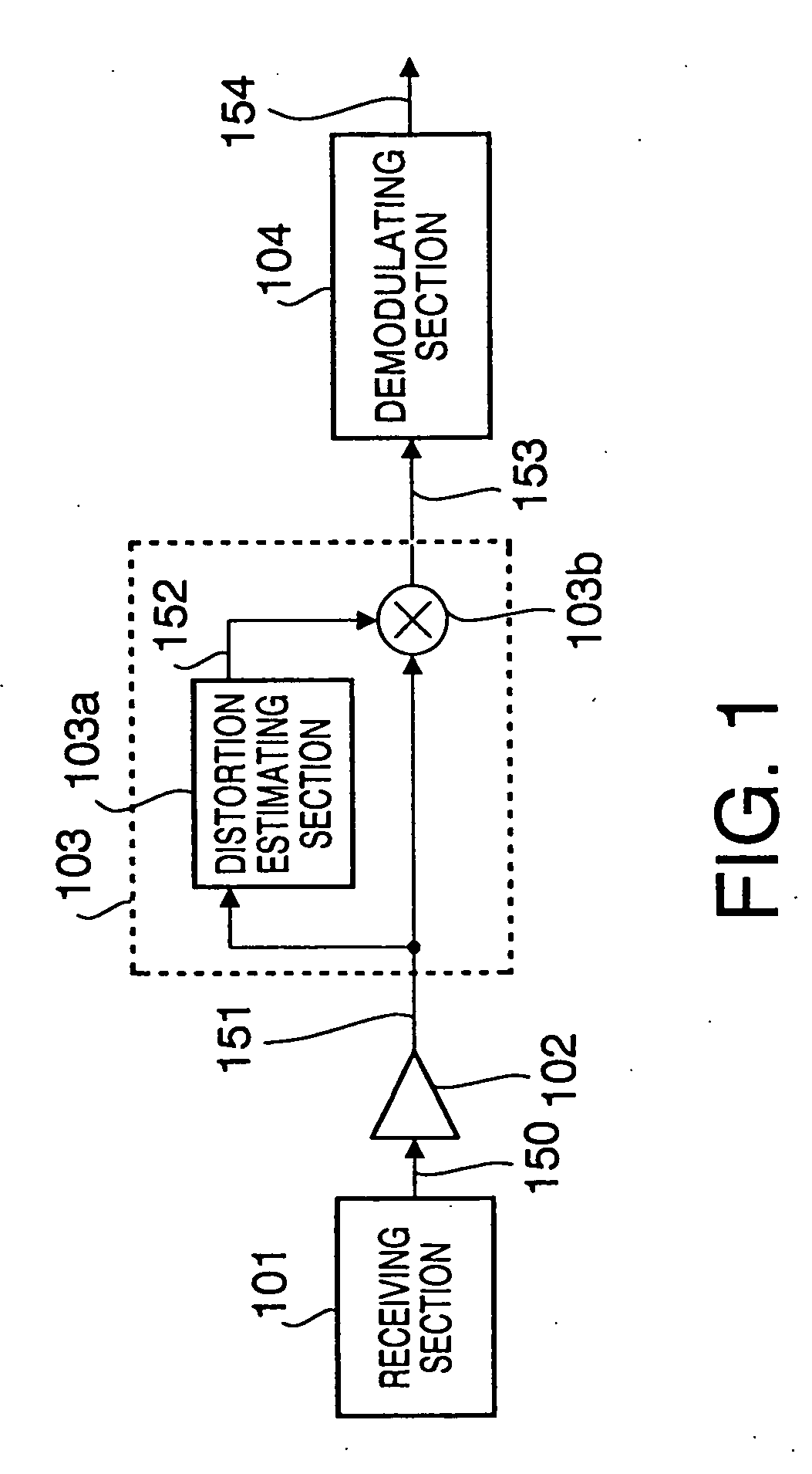
[0034]FIG. 1 is a block diagram illustrating a configuration of a digital reception apparatus according to the first embodiment of the present invention. The digital reception apparatus according to this embodiment is provided with receiving section 101, amplifying section 102, distortion correcting section 103 having distortion estimating section 103a and distortion compensating section 103b, and demodulating section 104.

[0035] The operation of the digital reception apparatus with the above configuration is explained. A signal transmitted from a transmitting-side apparatus (for example, a base station apparatus and mobile station apparatus) is received, through a propagation path, in receiving section 101 ...

second embodiment

[0054] (Second Embodiment)

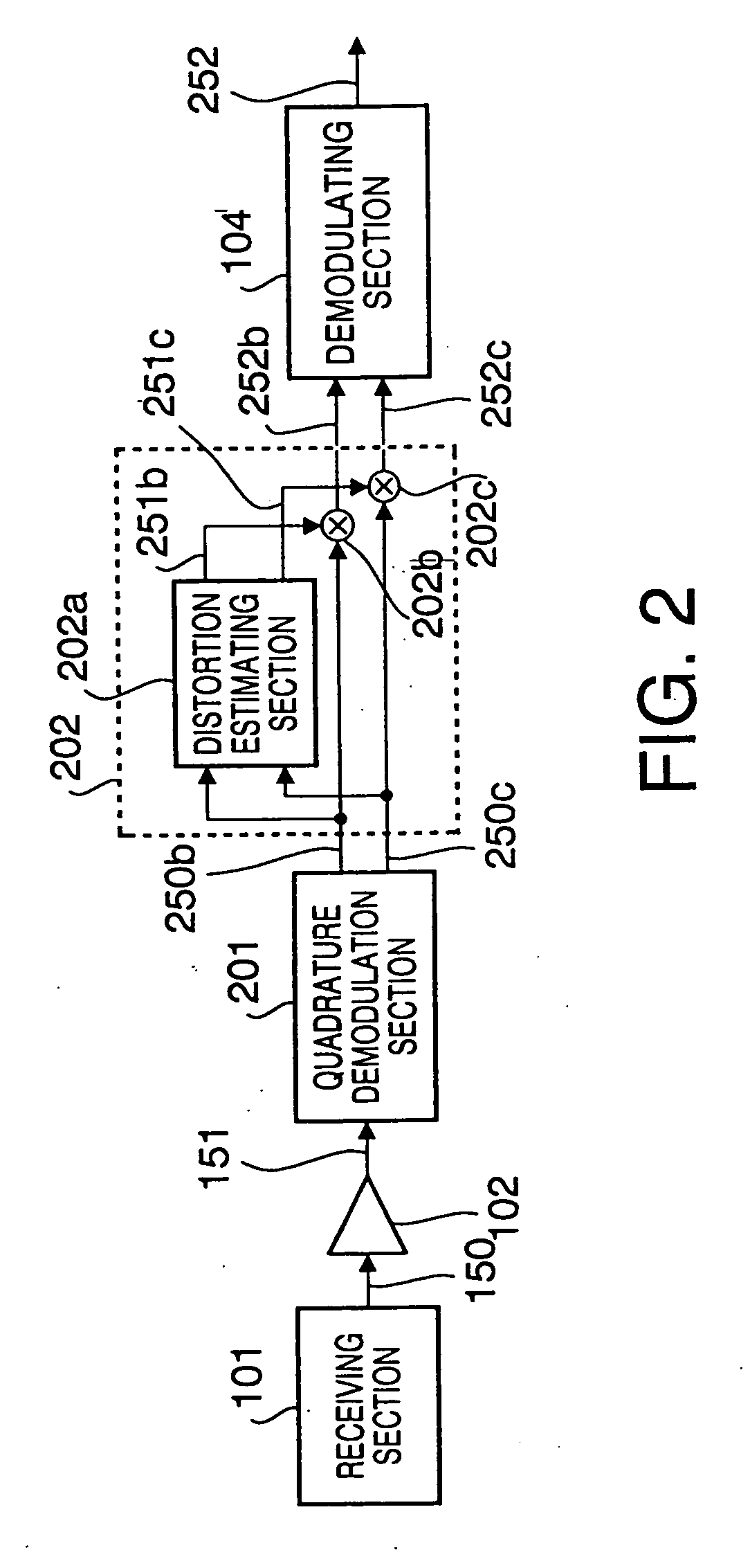
[0055]FIG. 2 is a block diagram illustrating a configuration of a digital reception apparatus according to the second embodiment of the present invention. In addition, in FIG. 2, the same sections as in the first embodiment (FIG. 1) are assigned the same reference numerals as in FIG. 1, and the detailed explanations are omitted.

[0056] The digital reception apparatus according to this embodiment is provided with receiving section 101, amplifying section 102, quadrature demodulation section 201, distortion correcting section 202 having distortion estimating section 202a and distortion compensating sections 202b and 202c, and demodulating section 104.

[0057] The operation of the digital reception apparatus with the above configuration is explained with attention only given to points different from the first embodiment.

[0058] The amplified signal 151 is demodulated in quadrature demodulation section 201 to be a baseband signal composed of an in-phase signal 2...

third embodiment

[0074] (Third Embodiment)

[0075]FIG. 3 is a block diagram illustrating a configuration of a digital reception apparatus according to the third embodiment of the present invention. In addition, in FIG. 3, the same sections as in the first embodiment (FIG. 1) are assigned the same reference numerals as in FIG. 1, and the detailed explanations are omitted.

[0076] The digital reception apparatus according to this embodiment is provided with receiving section 101, filtering section 301, quantizing section 302, distortion correcting section 303, and demodulating section 104.

[0077] The operation of the digital reception apparatus with the above configuration is explained with attention only given to points different from the first embodiment.

[0078] The received signal 150 from receiving section 101 is subjected the band limitation in filtering section 301 which cancels refrain errors and so on. A band limited signal 350 is thereby obtained. The obtained band limited signal 350 is output t...


PUM


Abstract

A digital reception apparatus includes a receiver that performs reception processing on a received signal and an adjuster that adjusts the amplitude of the received signal after the reception processing. A distortion estimator estimates a non-linear distortion of the received signal after the reception processing, the non-linear distortion being caused by the reception processing. A distortion corrector performs a distortion correction on the estimated non-linear distortion. A controller controls the adjuster based on a gain control signal such that the amplitude of a desired signal contained in the received signal after the reception processing and the distortion correction approaches a required level. The distortion estimator estimates the non-linear distortion of the received signal with reference to the gain control signal.

Description

[0001] The present application is a divisional application of pending U.S. patent application Ser. No. 09 / 813,856, filed on Mar. 22, 2001, which claims the benefit of Japanese Patent Application No. 2000-081226, filed on Mar. 23, 2000, the subject matter of which are expressly incorporated herein by reference in their entirety.BACKGROUND OF THE INVENTION [0002] 1. Field of the Invention [0003] The present invention relates to a reception apparatus used in a digital communication. [0004] 2. Description of the Related Art [0005] Conventionally, in a reception apparatus used in a digital communication (hereinafter referred to as “digital reception apparatus”), on the assumption that the linearity is maintained in the reception processing on received signals, the demodulation processing has been executed on the received signals subjected to the reception processing. When the linearity is not maintained in the reception processing on received signals, characteristics of demodulated signa...

Claims


Application Information

Patent Timeline
Patent Type & Authority Applications(United States)
IPC IPC(8): H04L27/08H04B1/10H03D3/00H03M1/00H04L27/00H04L27/06H04L27/22H04L27/38
CPCH04L27/2647H03D3/006
Inventor ORIHASHI, MASAYUKIABE, KATSUAKIMSUYA, JOB CLEOPATAKABAYASHI, SHINICHIRO
Owner PANASONIC CORP
Why Eureka
Try Eureka