Display
a display and display technology, applied in the field of display, can solve the problems of moiré effect and newton's ring effect, easy to occur, and increase the cost of the prism, so as to reduce the optical interference of the display and improve the picture quality
- Summary
- Abstract
- Description
- Claims
- Application Information
AI Technical Summary
Benefits of technology
Problems solved by technology
Method used
Image
Examples
first embodiment
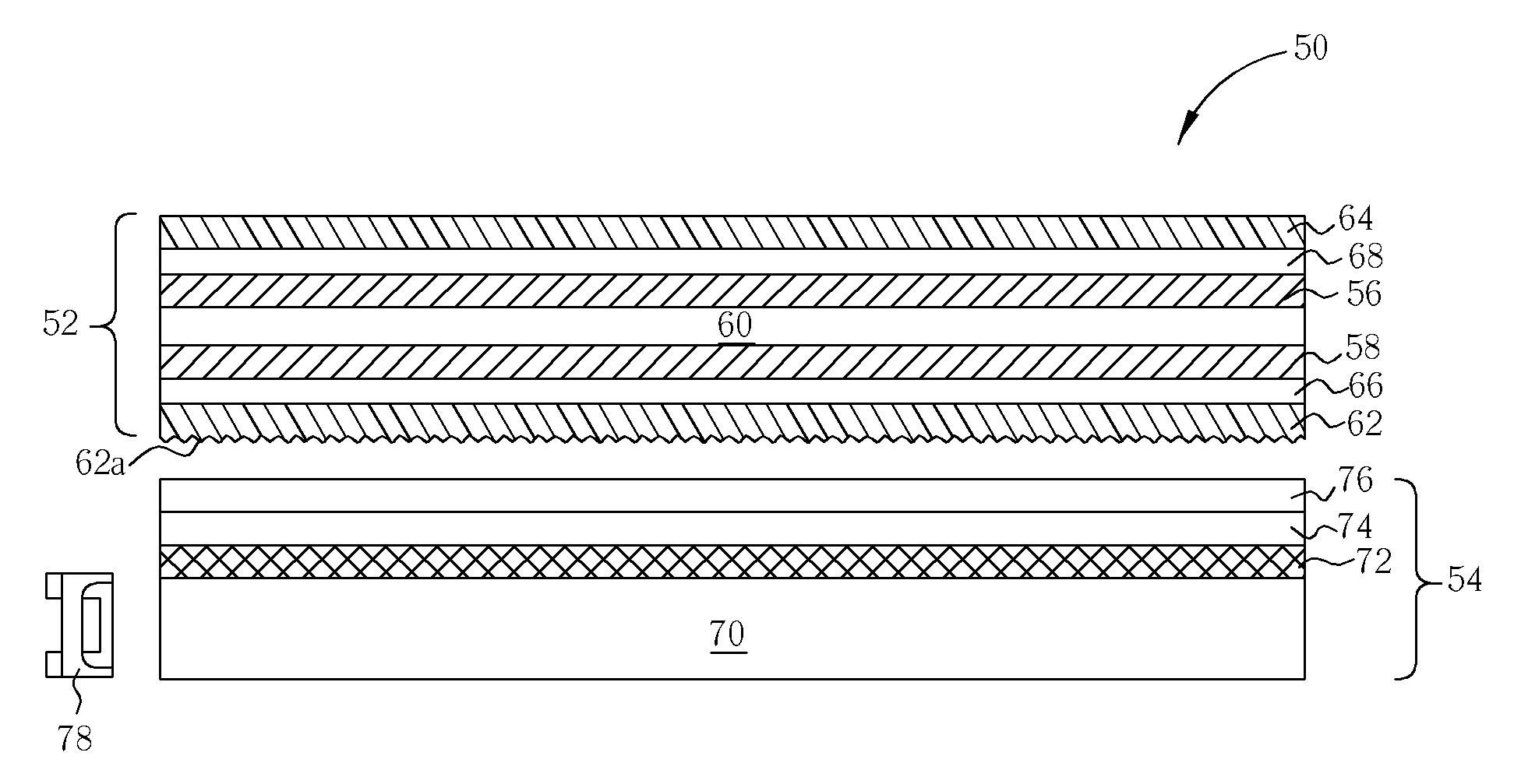
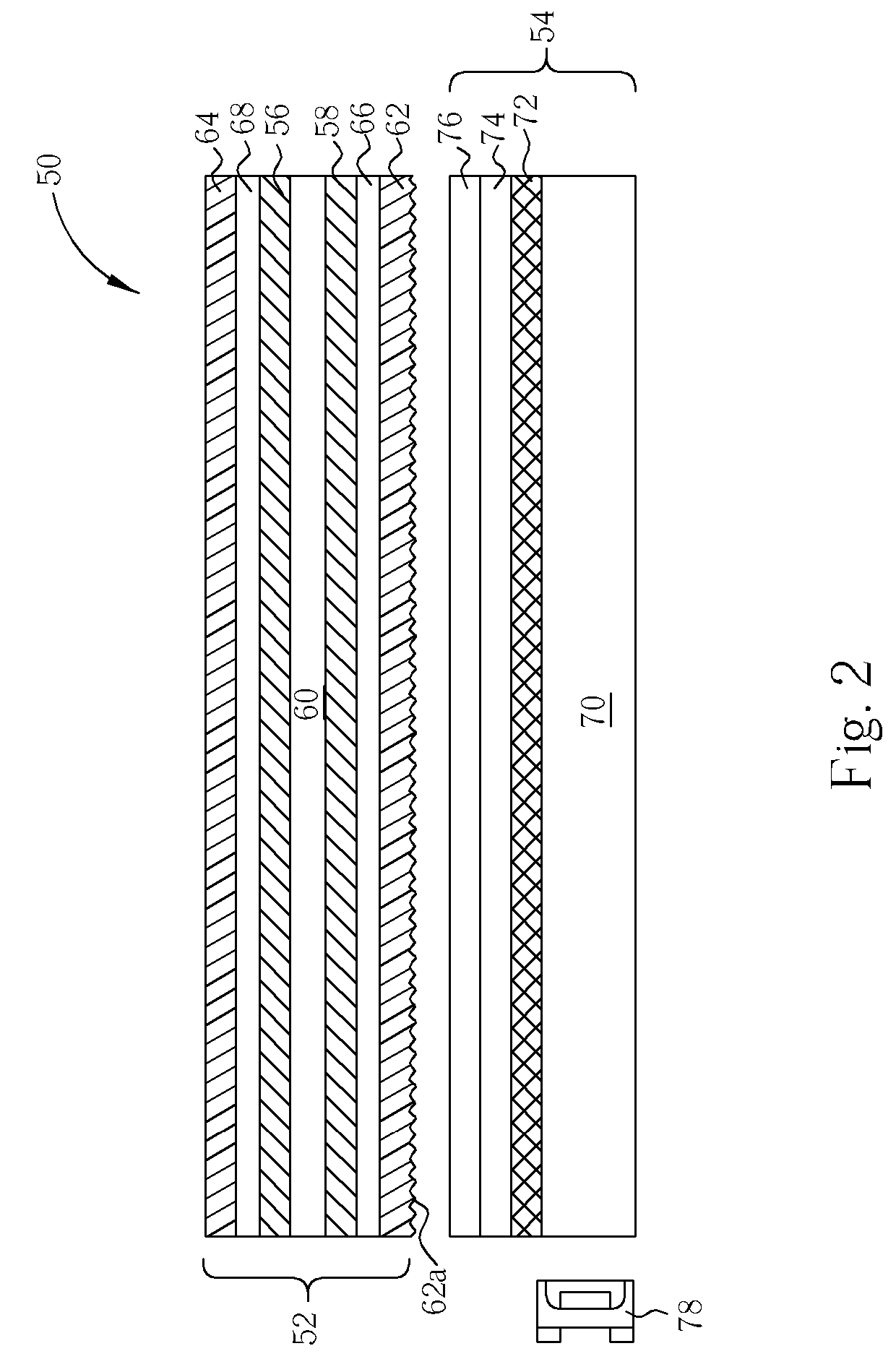
[0020] The flat display panel 152 comprises an upper transparent substrate 56, a lower transparent substrate 58, a liquid crystal layer 60 between the upper transparent substrate 56 and the lower transparent substrate 58, an upper polarizer 64 and a lower polarizer 62. The upper polarizer 64 and the lower polarizer 62 adhere to the upper surface of the upper transparent 56 with an upper adhesive 68 and the lower surface of the lower transparent substrate 58 with a lower adhesive 66 individually. The upper transparent substrate 56 and the lower transparent substrate 58 are made from nonconductors such as quartz or glass. The penetration axis of the upper polarizer 64 is perpendicular to the penetration axis of the lower polarizer 62. Please note that a diffusion layer is provided under the lower surface of the flat display panel 52 in the first embodiment to improve the optical interfere problem of the flat display panel 52. That means a rough lower surface 62a of the lower polarizer...
third embodiment
[0022] Please refer to FIG. 4. FIG. 4 is a diagram of a display module 100 according to the present invention. The display module 100 comprises a first part 102 and a second part 104. The first part 102 is a flat display panel 106, which comprises an upper glass substrate, a lower glass substrate, a liquid crystal layer, an upper polarizer 108 on the upper lateral of the flat display panel, and a lower polarizer 110 on the lower lateral of the flat display panel. The upper polarizer 108 is adhered to the surface of the flat display panel 106 by the upper adhesive 112, and the lower polarizer 110 is adhered to the surface of the flat display panel 106 by the lower adhesive 114. The second part 104 comprises a back light module, which comprises a light source (not shown), a light guide plate 115, a diffusion film 116, and two prisms 118, 120.
[0023] In the third embodiment, an upper surface 108a of the upper polarizer 108 undergoes a rough process, so the upper surface 108a is rough. O...
fifth embodiment
[0026] Please refer to FIG. 6. FIG. 6 is a cross-section diagram of a display module 200 according to the present invention. As mentioned above, the display module 200 comprises a first part 202 and a second part 204. The second part 204 is a back light module, which comprises a light source (not shown), a light guide plate 216, a diffusion film 218 and two prisms 222, 224 with perpendicular patterns. The first part 202 comprises a liquid crystal display panel 214, which has an upper polarizer 206 and a lower polarizer 208 adhere to the upper surface and the lower surface of the liquid crystal display panel 214 individually. There is an upper diffusing adhesive 210 between the upper polarizer 206 and the liquid crystal display panel 214, and a lower diffusing adhesive 212 between a lower polarizer 208 and the liquid crystal display panel 214. The upper spread adhesive 210 and the lower spread adhesive 212 are used to adhere the upper polarizer 206 and the lower polarizer 208 with th...
PUM
 Abstract
Description
Claims
Application Information
 - R&D
- Intellectual Property
- Life Sciences
- Materials
- Tech Scout
- Unparalleled Data Quality
- Higher Quality Content
- 60% Fewer Hallucinations
Browse by: Latest US Patents, China's latest patents, Technical Efficacy Thesaurus, Application Domain, Technology Topic, Popular Technical Reports.
© 2025 PatSnap. All rights reserved.Legal|Privacy policy|Modern Slavery Act Transparency Statement|Sitemap|About US| Contact US: help@patsnap.com


