Pole support tube
- Summary
- Abstract
- Description
- Claims
- Application Information
AI Technical Summary
Benefits of technology
Problems solved by technology
Method used
Image
Examples
Embodiment Construction
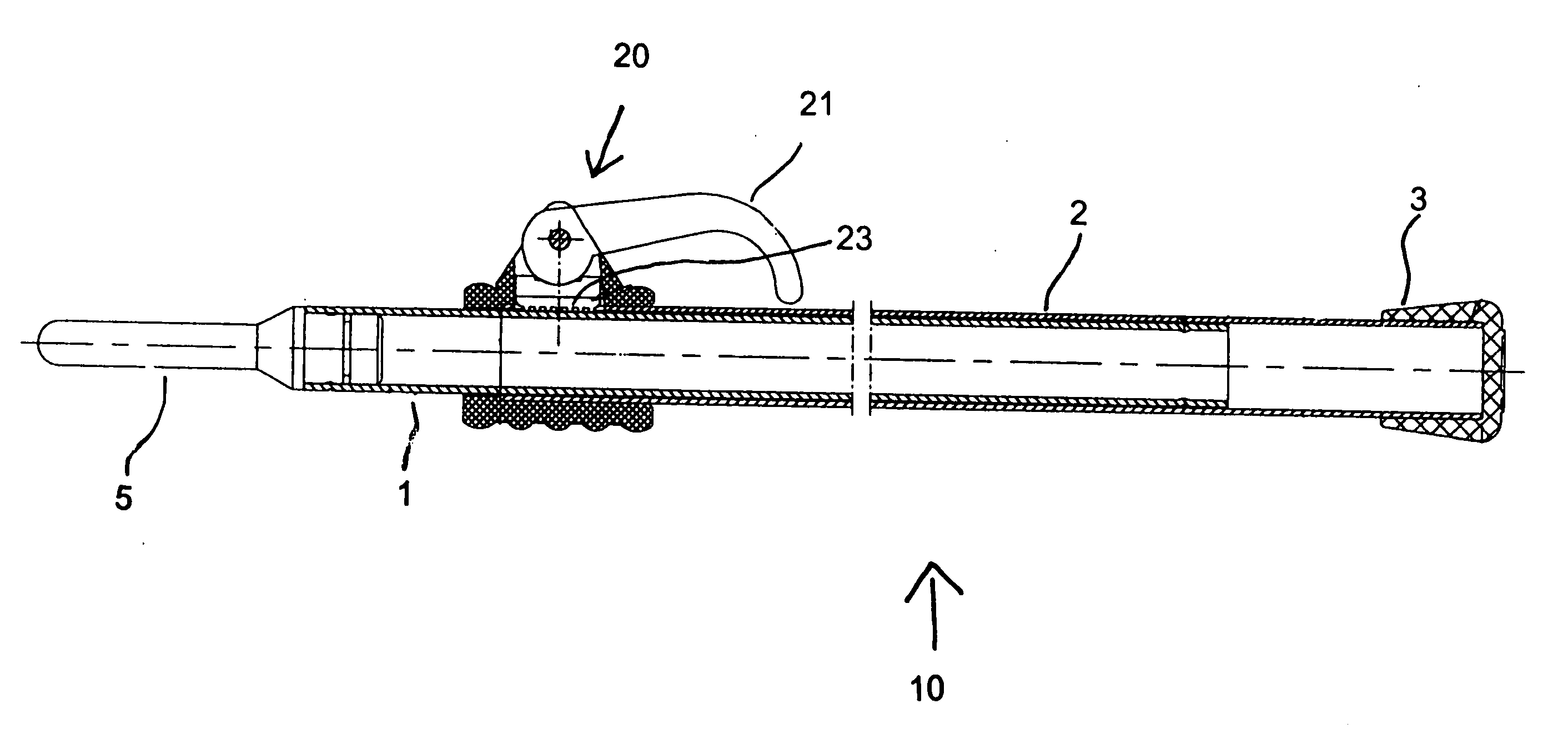
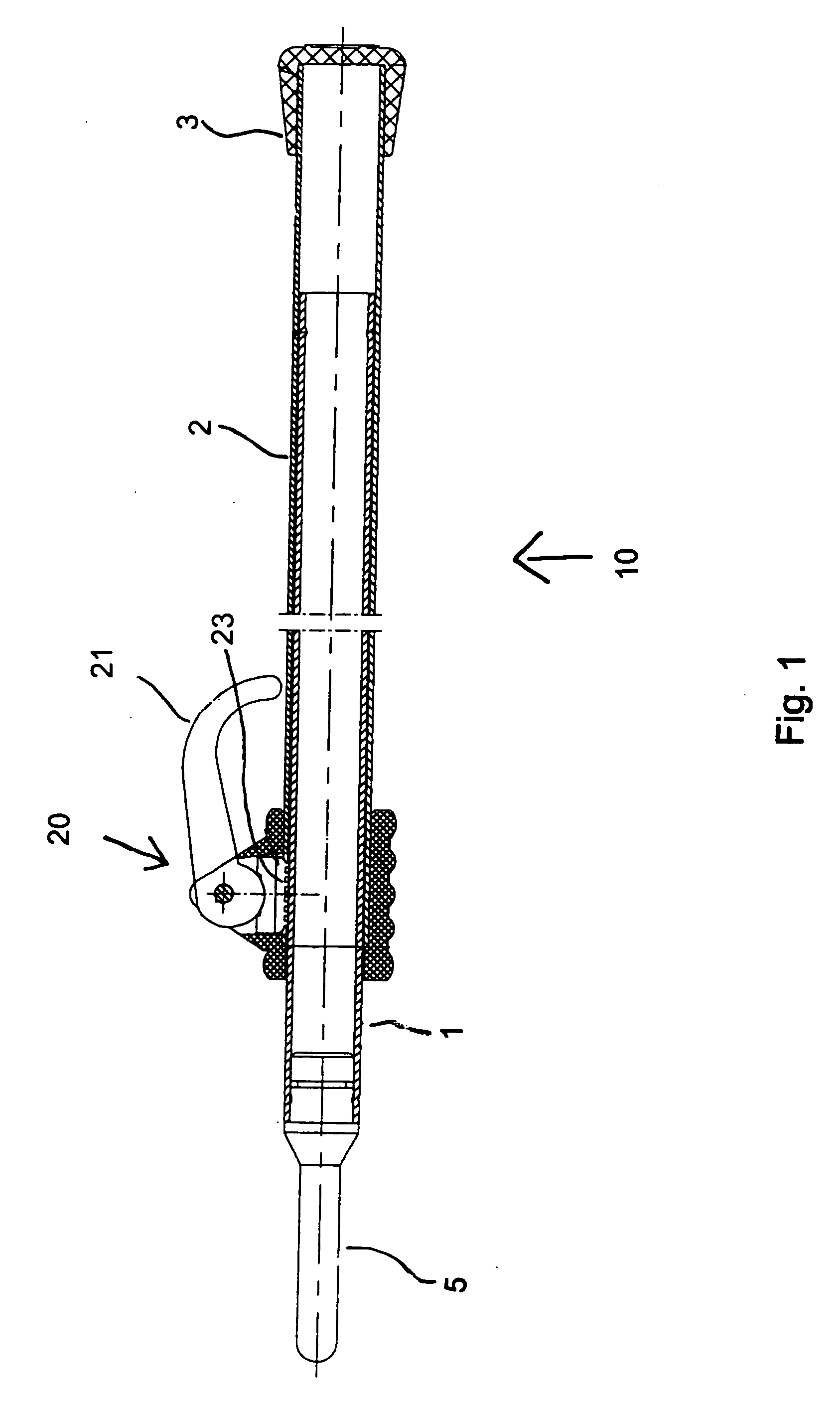
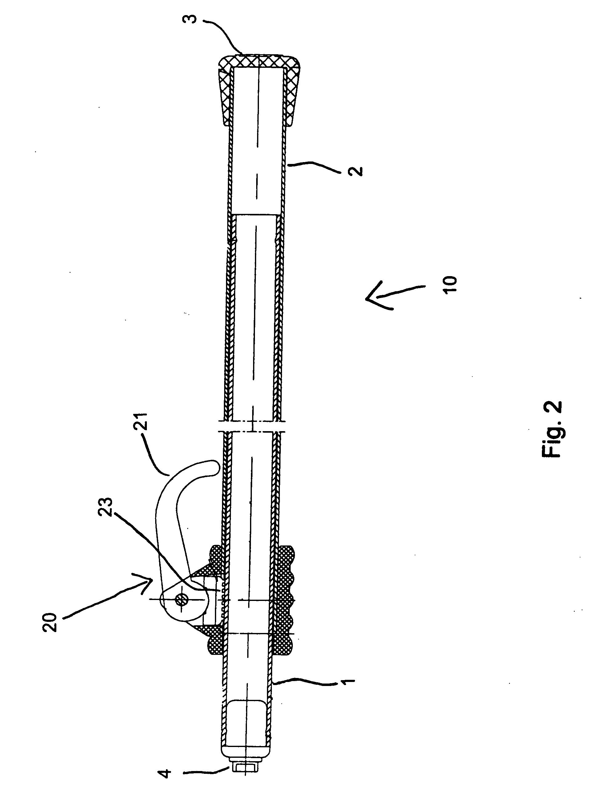
[0024] Referring now to the figures of the drawing in detail and first, particularly, FIGS. 1, 2, and 3 illustrate a pole support tube having an inner section or inner tube 1 and an outer section or outer tube 2. Included on a free end of the outer section 2 is a rubber foot 3. The inner section includes either a universal snap end 4 (FIG. 2) or a tent pole type end 5 (FIG. 2), or as shown in FIG. 3 the inner section 1 can have both the universal snap 4 and the tent pole type end 5 on opposite ends thereof.
[0025] The pole support tube 10 can be adjusted to infinite extended lengths by a cam assembly 20. The cam assembly 20 is disposed on the outer section 2 at the outer diameter of the outer section 2. The cam assembly 20 includes a rotatable lever 21 that allows for a quick and easy setting of the length of the pole support tube. The lever 21 activates a pressure pad 23 that engages the outer diameter of the inner section 1 through a hole formed in the outer section. In the activa...
PUM
 Abstract
Description
Claims
Application Information
 - R&D
- Intellectual Property
- Life Sciences
- Materials
- Tech Scout
- Unparalleled Data Quality
- Higher Quality Content
- 60% Fewer Hallucinations
Browse by: Latest US Patents, China's latest patents, Technical Efficacy Thesaurus, Application Domain, Technology Topic, Popular Technical Reports.
© 2025 PatSnap. All rights reserved.Legal|Privacy policy|Modern Slavery Act Transparency Statement|Sitemap|About US| Contact US: help@patsnap.com


