Eureka AIR delivers breakthrough ideas for toughest innovation challenges, trusted by R&D personnel around the world.

Tamper resistant temperature dial utilizing deflection pins

a technology of deflection pins and temperature dials, which is applied in the direction of mechanical control devices, wing knobs, instruments, etc., can solve the problems of affecting the installation, replacement or service of water heaters, water to issue at unexpectedly high temperatures, and additional cost and/or inconvenience in us

Inactive Publication Date: 2006-10-26
ROBERTSHAW CONTROLS CO
View PDF36 Cites 2 Cited by
  • Summary
  • Abstract
  • Description
  • Claims
  • Application Information

AI Technical Summary

Benefits of technology

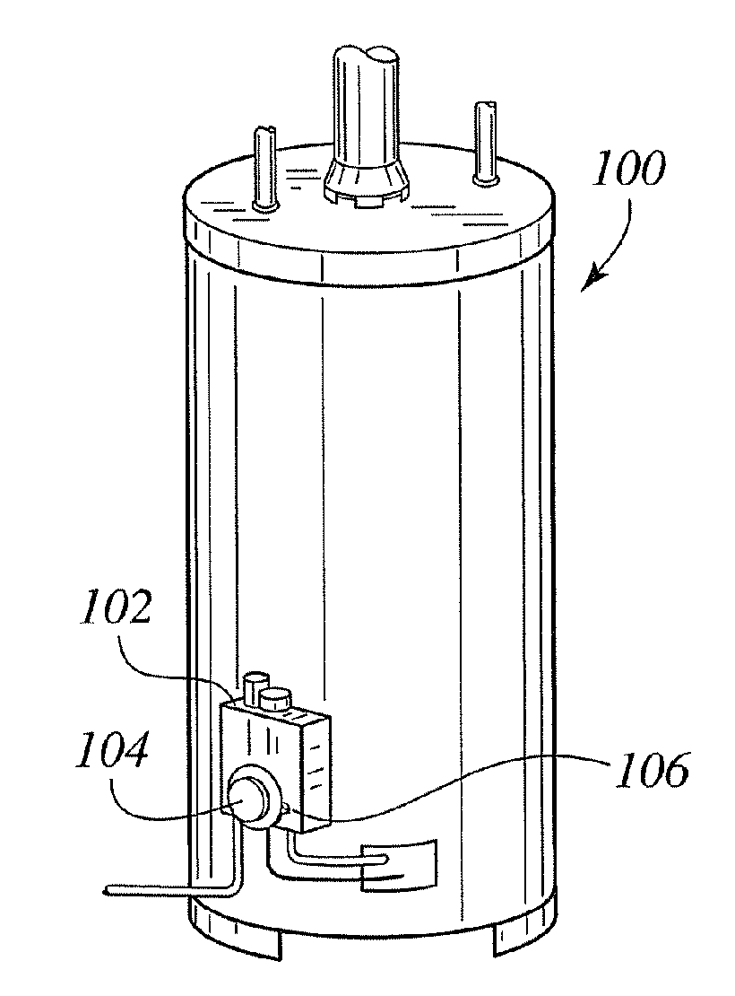
[0008] This invention relates generally to temperature control dials and, more particularly, to tamper resistant temperature control dials for a heating device, such as for example a hot water heater.

Problems solved by technology

Excessive water temperature is a hazard in that it may cause scalding at any of the various faucets or appliances serviced by the water heater.
Accidental or inadvertent adjustment of the temperature dial can cause water to issue at unexpectedly high temperatures.
Properly securing a water heater from this type of tampering typically results in additional cost and / or inconvenience as to its use.
An enclosure may also hamper the installation, replacement, or servicing of the water heater.
Some of the devices that have previously been developed that are associated directly with a control knob or valve to prevent tampering either involve a substantial additional cost of manufacturing or are very inconvenient to use.
In addition to the increased costs in manufacturing, such devices are often difficult to retrofit to existing installations.
As such, a significant problem is the inadvertent adjustment of a temperature dial and the lack of a solution that does not involve a major inconvenience or increased manufacturing costs.

Method used


Image

  • Tamper resistant temperature dial utilizing deflection pins
  • Tamper resistant temperature dial utilizing deflection pins
  • Tamper resistant temperature dial utilizing deflection pins

Examples


Embodiment Construction

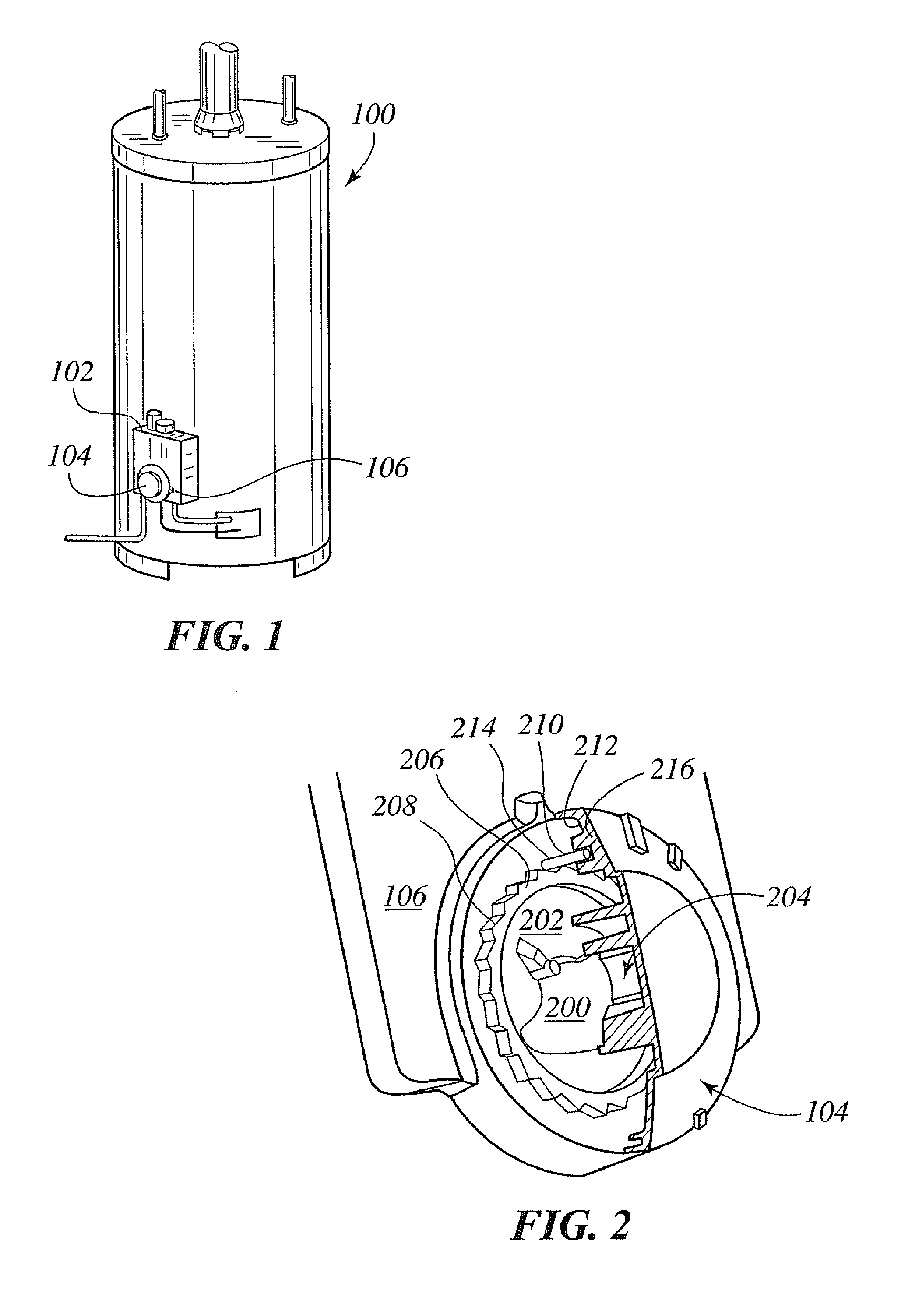
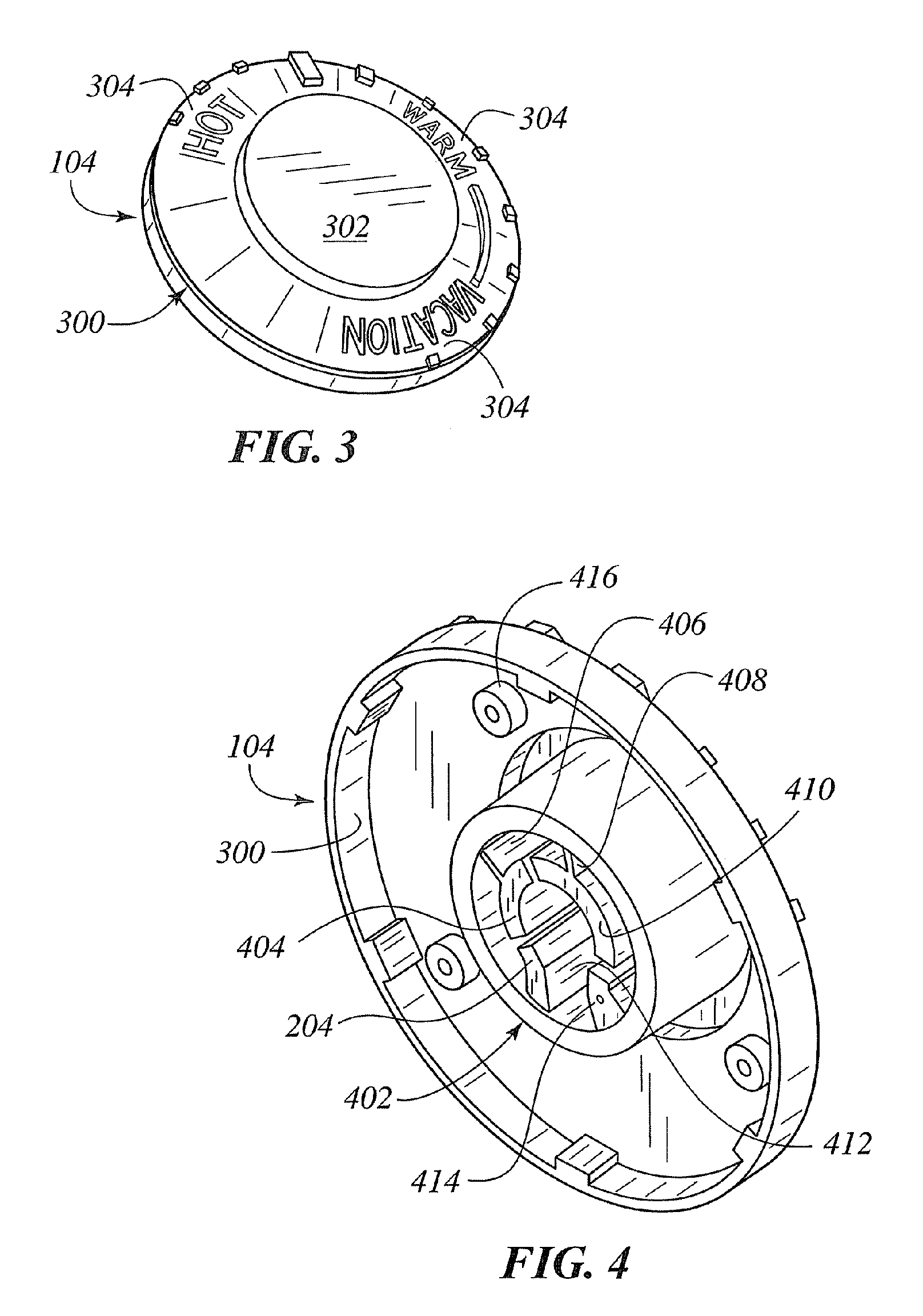
[0020] According to the embodiment(s) of the present invention, various views are illustrated in FIGS. 1-4 and identical reference numerals are being used consistently throughout to refer to the same parts of the invention for all of the various views and figures of the drawing. Please note that the first digit(s) of the reference number for a given item or part of the invention should correspond to the FIG. number in which the item or part is first identified.

[0021] One embodiment of the present invention comprising an adjustment interface for adjusting a controller teaches a novel apparatus and method for controlling the temperature of a heating device comprising a controller cover panel having a rotatable controller adjustment member having an end portion extending through an opening of the controller cover panel beyond an exterior surface of said controller cover panel, wherein said rotatable controller adjustment member is operable to adjust a controller when said rotatable me...


PUM


Abstract

An adjustment interface for adjusting a controller teaches a novel apparatus and method for controlling the temperature of a heating device comprising a controller cover panel having a rotatable controller dial; a ring member mounted to axially extend beyond and away from the exterior surface, wherein the ring member has projections radially extending from an exterior perimeter of the ring member; and said rotatable controller is operatively connectable to a rotatable controller adjustment and said control dial operable to effect rotation of the rotatable adjustment member when said control dial is grasped and turned and said control dial having a deflection pin extending therefrom having sufficient length and orientation to crossingly engage the projections extending from the exterior perimeter of the ring member such that the deflection pin resistively engages the projections and flexes to travel radially over and disengaging the projections when the control member is turned.

Description

BACKGROUND OF THE INVENTION [0001] The temperature of the water within a water heater is usually maintained and adjusted by a rotatable temperature dial. In the case of a gas-fired water heater, there is a temperature dial that is operatively connected to a gas controller valve that directs the flow of gas to a burner whenever the temperature of the water falls below the set temperature. For an electric water heater, there is a temperature dial that is operatively connected to a thermostat that directs electricity to a heating element whenever the temperature of the water falls below the set temperature. [0002] Excessive water temperature is a hazard in that it may cause scalding at any of the various faucets or appliances serviced by the water heater. Accidental or inadvertent adjustment of the temperature dial can cause water to issue at unexpectedly high temperatures. [0003] The temperature dial is located in a position that is typically, easily reached and rotated. If the water ...

Claims


Application Information

Patent Timeline
Patent Type & Authority Applications(United States)
IPC IPC(8): H05B1/02
CPCF24H9/20Y10T74/2084G05G1/10Y10T292/82F24H15/37F24H9/25F24H15/31
Inventor NGUYEN, CAN TRONGJOUBRAN, RAYMOND-PAUL
Owner ROBERTSHAW CONTROLS CO
Why Eureka
Eureka Blog
Learn More