Eureka AIR delivers breakthrough ideas for toughest innovation challenges, trusted by R&D personnel around the world.

Lobular drive system with interference fit and method and apparatus for fabricating same

a drive system and interference fit technology, applied in the direction of threaded fasteners, forging/hammering/pressing machines, screw heads, etc., can solve the problems of excessive bit wear, high mechanical stress at these limited locations, damage to workpieces, etc., and achieve the effect of rotating out of the recess

Inactive Publication Date: 2009-01-01
ACUMENT INTPROP LLC
View PDF21 Cites 14 Cited by
  • Summary
  • Abstract
  • Description
  • Claims
  • Application Information

AI Technical Summary

Benefits of technology

[0010]Another object of an embodiment of the present invention is to provide a lobular drive system which provides an enhanced interference fit.
[0012]Yet another object of an embodiment of the present invention is to provide a lobular drive system which provides some measure of tamper resistance.
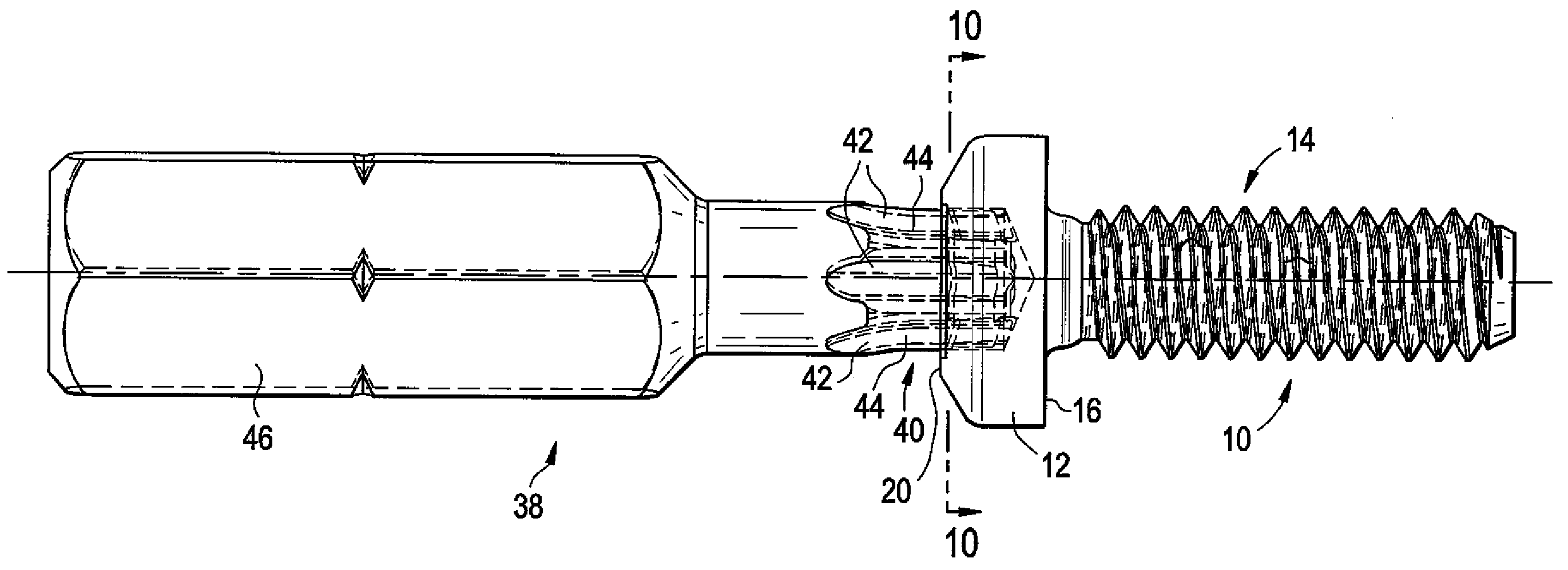
[0014]For example, a specific embodiment of the present invention which is illustrated herein is in the form of a fastener which includes a socket or recess that includes a plurality of alternating lobes and recesses, where each of the lobes and recesses are twisted or angled. The fact that each of the lobes and recesses are twisted or angled provides an enhanced interference fit in the form of at least two contact points per lobe—one on a leading edge of the lobe, and one on a trailing edge—as well as a measure of tamper resistance.
[0018]Still yet another embodiment of the present invention which is illustrated herein is a device which is configured to retain and use the punch pin to punch the recess into the head of the fastener. The device may include, for example, a pin holder, bearing and packing that are all disposed in a casing. The device is configured to retain the punch pin in a manner such that the punch pin is free to spin while being retained. As such, the device can be used to punch the head of the punch pin into the head of the fastener, and as the head of the punch pin is withdrawn from the recess which has been formed in the fastener, the head of the punch pin can effectively rotate out of the recess.

Problems solved by technology

Additionally, the particular construction of the '246 patent helps to prevent “walking” or “wobble” of a fastener, which can cause damage to workpiece.
Because wedging between the bit and the socket occurs only at outside edges of the lobes of the drive bit, high magnitude mechanical stresses can build up at these limited locations.
This stress concentration can cause excessive bit wear, as well as loss of dimensional tolerances.
Furthermore, because of the limited contact between the bit and the fastener, a natural tendency arises causing the bit to cam out of the socket in the fastener.
Accordingly, there is a potential that the effective lifetime of the drive bit will suffer a reduction, viz. a reduction in ability to prevent wobble, as well as a reduction in the integrity of an interference fit between the bit and the fastener which can make one-handed manual installation more difficult.
Additionally, variations in socket fall away, as measured across the major diameter of the socket, which may be difficult to eliminate, can adversely affect depth of penetration of the drive bit into the socket, thereby adding variability of insuring sufficient bit penetration into the socket for driving of the fastener.
Due to tolerances and wear during use, engagement may occur at fewer contact points per lobe or at fewer than all of the lobes.

Method used


Image

  • Lobular drive system with interference fit and method and apparatus for fabricating same
  • Lobular drive system with interference fit and method and apparatus for fabricating same
  • Lobular drive system with interference fit and method and apparatus for fabricating same

Examples


Embodiment Construction

[0036]While this invention may be susceptible to embodiment in different forms, there are shown in the drawings and will be described herein in detail, specific embodiments with the understanding that the present disclosure is to be considered an exemplification of the principles of the invention, and is not intended to limit the invention to that as illustrated.

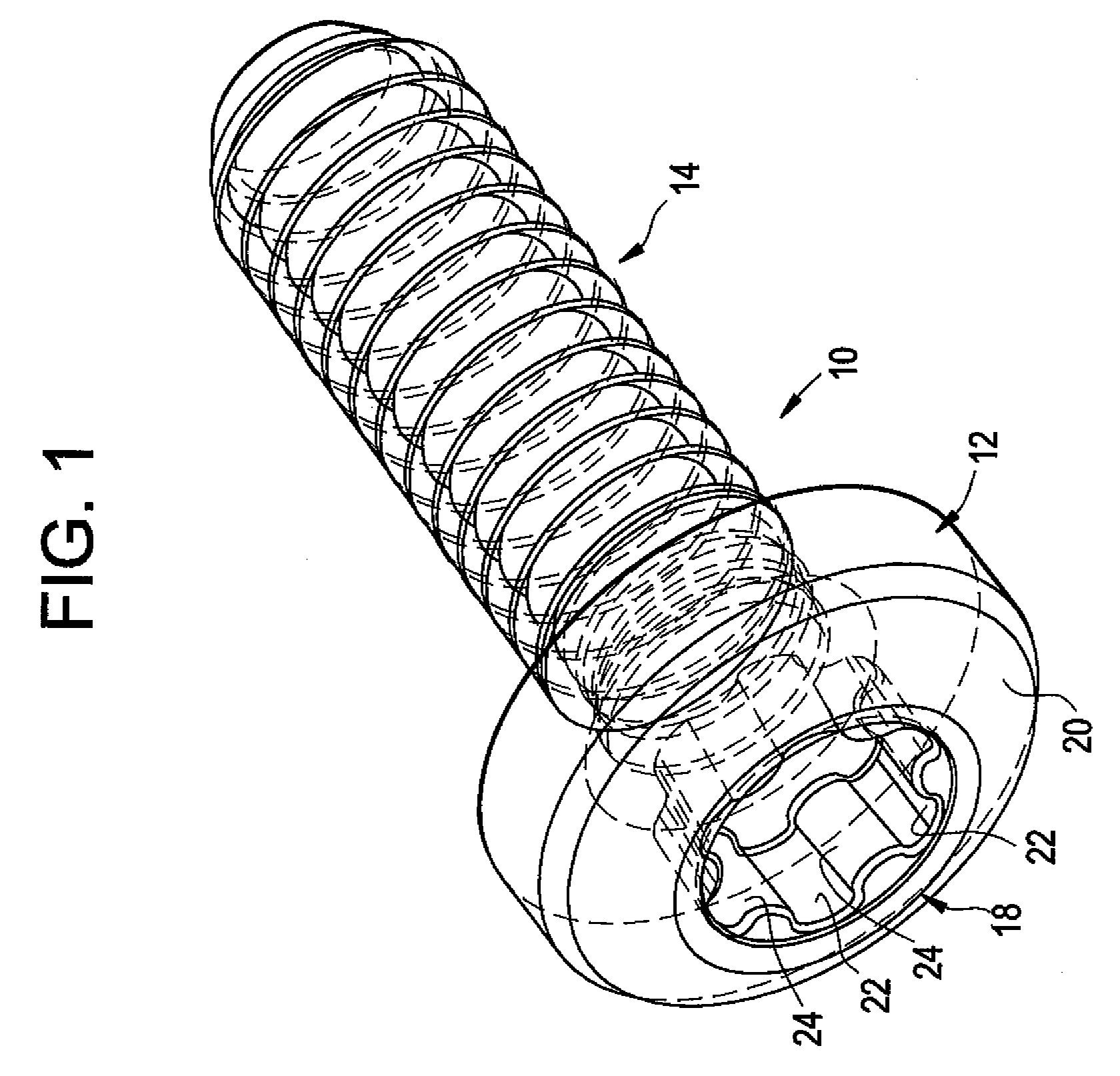
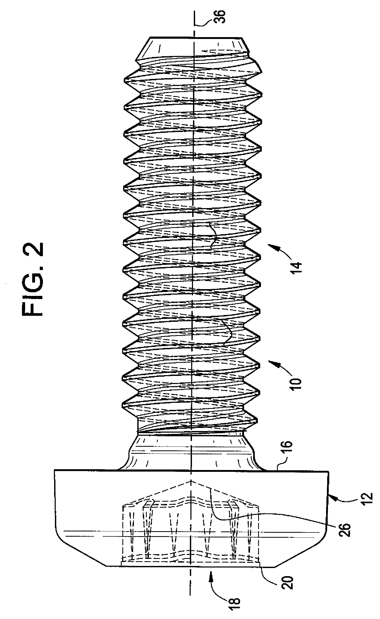
[0037]FIGS. 1-4 illustrate a fastener 10 which is in accordance with an embodiment of the present invention. The fastener 10 includes a head portion 12, and a threaded shaft portion 14 which extends from a bottom 16 of the head portion 12. A socket or recess 18 is provided in a top 20 of the head portion 12, and the recess 18 includes alternating flutes 22 and lobes 24, and a bottom 26 of the recess. 18 is generally conical. Although a different number of flutes and lobes can be provided, preferably there are six lobes 24 and six flutes 22, wherein each is spaced equidistantly along the circumference of the recess with adjac...


PUM

PropertyMeasurementUnit
Angleaaaaaaaaaa
Angleaaaaaaaaaa
Circumferenceaaaaaaaaaa

Abstract

A fastener which includes a recess that includes a plurality of alternating lobes and recesses, where each of the flutes and lobes is twisted or angled. The fastener can be driven using a conventional multi-lobular driver. Alternatively, a driver which also has angled or twisted flutes and lobes can be used to engage the recess and drive the fastener. A punch pin includes a head that has a plurality of alternating lobes and recesses that are twisted or angled. The head of the punch pin is configured to punch the recess into the head of the fastener. A device retains the punch pin such that the punch pin can rotate out of the recess after the punch pin punches the recess into the head of the fastener.

Description

RELATED APPLICATION (PRIORITY CLAIM) [0001]This application claims the benefit of U.S. Provisional Application Ser. No. 60 / 947,041, filed Jun. 29, 2007, which is hereby incorporated herein by reference in its entirety.BACKGROUND OF THE INVENTION[0002]The present invention generally relates to lobular drive systems, and more specifically relates to a lobular drive system and method and apparatus for fabricating same.[0003]Fasteners are a critical component of many structures and mechanisms, from the simplest machine to a highly complex space shuttle. Because of the critical functions performed by these fasteners, improvements in their structure and functional properties are continually sought. One such improvement is the TORX® brand drive system, which can be employed, for example, in a drive socket or on a head portion of a fastener, or on a drive bit or socket used for driving such a fastener into a workpiece.[0004]The construction and benefits of the TORX® brand drive system are d...

Claims


Application Information

Patent Timeline
IPC IPC(8): F16B23/00B23G9/00
CPCB21K1/463F16B23/0038B25B15/005
Inventor LUNA, DENNIS
Owner ACUMENT INTPROP LLC
Why Eureka
Eureka Blog
Learn More