
Controller for continuously variable transmission

a technology of transmission control and control box, which is applied in non-electric variable control, process and machine control, instruments, etc., can solve the problems of affecting the control of speed ratio relative to the cvt, reducing driving torque, and unable to maintain the speed of the vehicle at 60 km/h, so as to achieve the effect of preventing engine output control and simplifying construction

Active Publication Date: 2006-10-19
MITSUBISHI MOTORS CORP
View PDF6 Cites 8 Cited by
  • Summary
  • Abstract
  • Description
  • Claims
  • Application Information

AI Technical Summary

Benefits of technology

[0014] The present invention has been made in view of the circumstances described above. Accordingly, it is the primary object of the present invention to provide a structurally simpler controller for a continuously variable transmission which is capable of preventing the engine output control from interfering with the speed ratio control relative to the CVT during travel at a constant speed.
[0016] Thus, with a simpler construction, the engine output control can be prevented from interfering with the speed ratio control relative to the CVT during travel at a constant speed.

Problems solved by technology

When the vehicle speed Vs is being held constant, there are cases where engine output control (e.g., control of throttle opening) interferes with speed ratio control relative to the CVT.
As a result, the driving torque will be reduced and the vehicle speed cannot maintain a speed of 60 km / h.
The technique shown in the aforementioned Japanese Laid-Open Patent Publication, however, requires mathematical modeling of a vehicle and a control program therefor, which are fairly difficult and time-consuming.
Moreover, fine adjustments to them involve considerable time, labor, and costs.

Method used


Image

  • Controller for continuously variable transmission
  • Controller for continuously variable transmission
  • Controller for continuously variable transmission

Examples


Embodiment Construction

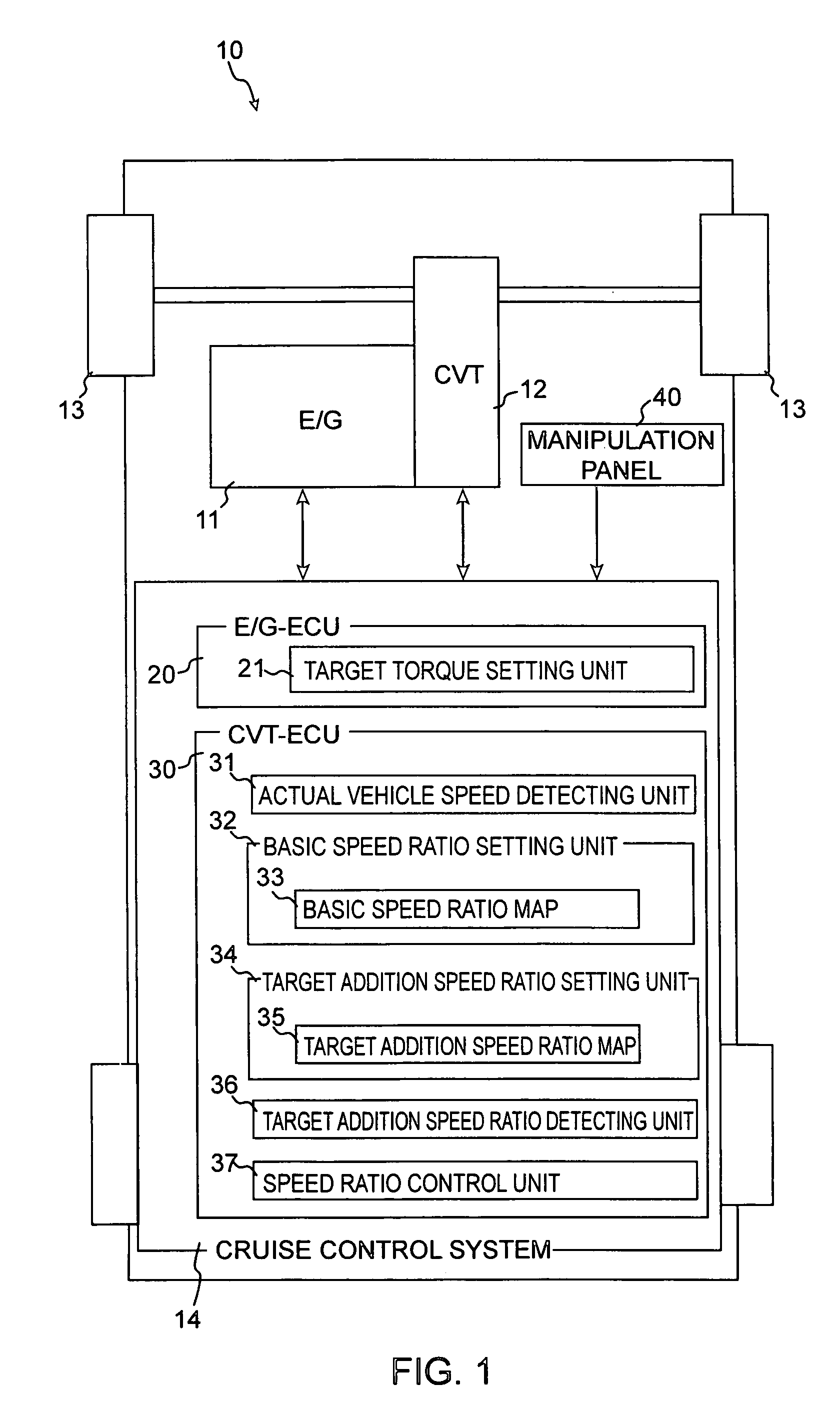
[0024] Referring to FIG. 1, there is shown a controller for a continuously variable transmission constructed in accordance with a preferred embodiment of the present invention. As shown in the figure, a vehicle 10 includes a gasoline engine (hereinafter referred to simply as an engine (E / G)) 11 and a continuously variable transmission (CVT) 12 by which torque output from the engine 11 is transmitted to driving wheels 13. The engine 11 is equipped with an electronically controlled throttle valve (not shown), its throttle opening being controlled by an engine electronic control unit (E / G-ECU) 20 to be described later.

[0025] The vehicle 10 further includes a cruise control system 14 that can be switched on to maintain a target vehicle speed VS-T without the use of the accelerator pedal. The cruise control system 14 is connected with the engine 11 and CVT 12 and is mainly equipped with the E / G-ECU 20 and a CVT electronic control unit (CVT-ECU) 30.

[0026] The cruise control system 14 is...


PUM


Abstract

A controller for a continuously variable transmission (CVT) mounted in a vehicle. The controller includes a first setting unit for setting a basic speed ratio of the CVT; a second setting unit for setting an adjustment speed ratio of the CVT; and a control unit for controlling the CVT based on the basic speed ratio and adjustment speed ratio. The second setting unit includes an increasing unit for progressively increasing the adjustment speed ratio according to a decrease in a target torque interrelated value in a first operating area, and a decreasing unit for progressively decreasing the adjustment speed ratio according to a decrease in the target torque interrelated value in a second operating area. Between the first operating area and the second operating area, the second setting unit maintains the adjustment speed ratio that is set finally.

Description

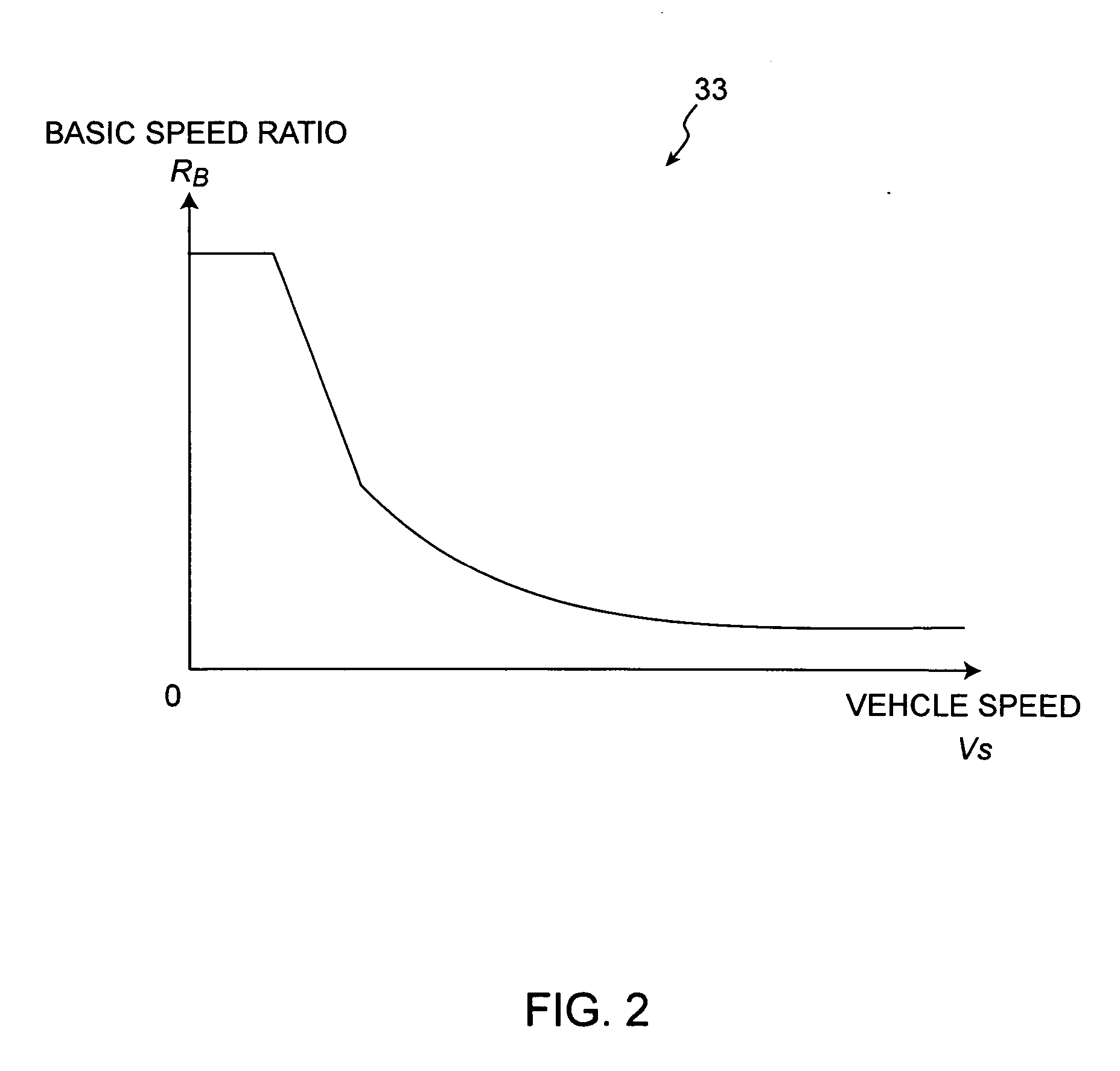
CROSS-REFERENCE TO THE RELATED APPLICATION [0001] This application incorporates by references the subject matter of Application No. 2005-117065 filed in Japan on Apr. 14, 2005 on which a priority claim is based under 35 U.S.C. § 119(a). BACKGROUND OF THE INVENTION [0002] (1) Field of the Invention [0003] The present invention relates to a controller for a continuously variable transmission that is particularly suitable for use in vehicles. [0004] (2) Description of the Related Art [0005] Vehicles with a continuously variable transmission (CVT) have hitherto been put to practical use and are able to enhance fuel consumption while preventing a shock that is caused in changing vehicle speed. [0006] The continuously variable transmission is designed so that stepless speed ratios are obtained. The speed ratios, as shown in FIG. 6, are produced based on a basic speed ratio RB100 previously set according to a vehicle speed Vs. If the accelerator pedal is depressed, the basic speed ratio RB...

Claims


Application Information

Patent Timeline
IPC IPC(8): G06F17/00
CPCY10T477/6223F16H61/66259
Inventor SUZUKI, YUJIOHTA, TAKASHIHANAI, YOSUKEIZUMI, HIROSHI
Owner MITSUBISHI MOTORS CORP
Learn More