
Method for reverse link congestion overload control in wireless high speed data applications

a high-speed data and reverse link technology, applied in the field of reverse link congestion overload control, can solve the problems of reducing the performance of all ats, radio link cannot handle the number of ats, discontinuous high-speed data transmitted by ats, etc., and achieve the effect of distributing fairness

Inactive Publication Date: 2006-10-19
RPX CORP
View PDF6 Cites 32 Cited by
  • Summary
  • Abstract
  • Description
  • Claims
  • Application Information

AI Technical Summary

Benefits of technology

[0006] In accordance with an embodiment of the present invention, the value of a congestion overload metric is used as a Congestion Overload Control (COC) on the reverse link to transition the wireless system between a normal state, a block state, and a mute state. The system is shifted from the normal state into the block state when the value of the CO metric reaches a first predetermined threshold that is indicative of a first level of congestion due to too much traffic the reverse link, and is shifted into the mute state when the value of the CO metric increases to a higher second predetermined threshold value that is indicative of an even higher level of congestion on the reverse link. In the block state, new calls by attempting ATs are not admitted into the system. In the mute state, at least some of the active and connected ATs are instructed to decrease their transmit rates to zero, while still maintaining their active connection with the base station. When the value of the CO metric decreases, the system is shifted back to the block state, and eventually back to the normal state when the value of the CO metric reaches another predetermined threshold that is indicative of a normal condition.
[0007] In an exemplary embodiment of the invention, a filtered number of RAB equal to “1” per frame is the metric used to determine whether the reverse link in a wireless system is in a congestion overload state due to a reverse link RF overload. In the normal state, the ROC controls the transmission rates of the ATs on the reverse link in accordance with the “1” and “0” values of the changing RABs sent downlink to the active ATs by the BTS. When the value of the CO metric exceeds the first predetermined threshold that is indicative of a congestion overload condition, the system enters the block state where all new connection requests are blocked. Once in the block state, if the value of the CO metric does not decrease but continues to increase and exceeds the second higher threshold, the system enters the mute state. In the mute state a predetermined large percentage of existing active calls are muted. Specifically, a message is sent downlink to specific ATs instructing them to reduce their transmission rates to zero but to still maintain their active connections. If, after a predetermined interval, the value of the CO metric still exceeds the second threshold, an additional number of ATs are instructed to reduce their transmission rates to zero...

Problems solved by technology

Unlike other traffic, such as voice, which is continuous in nature, the high-speed data transmitted by an AT is generally discontinuous and bursty.
With so many data calls involved in established data connections, there are times when the radio link cannot handle the number of ATs actually simultaneously transmitting on the RL at the rate they desire.
When such a CO condition occurs, the performance levels of all the ATs decrease so that they are unable to meet their required minimum FER.
Meanwhile, during congestion overload, new calls continue to be admitted to the system further exacerbating the situation.
Dropping calls creates its own deleterious side effects as network resources are wasted in reconnecting the dropped calls.
Furthermore, reconnection requests sent by the dropped ATs create additional interference on the already congested system.

Method used


Image

  • Method for reverse link congestion overload control in wireless high speed data applications
  • Method for reverse link congestion overload control in wireless high speed data applications
  • Method for reverse link congestion overload control in wireless high speed data applications

Examples


Embodiment Construction

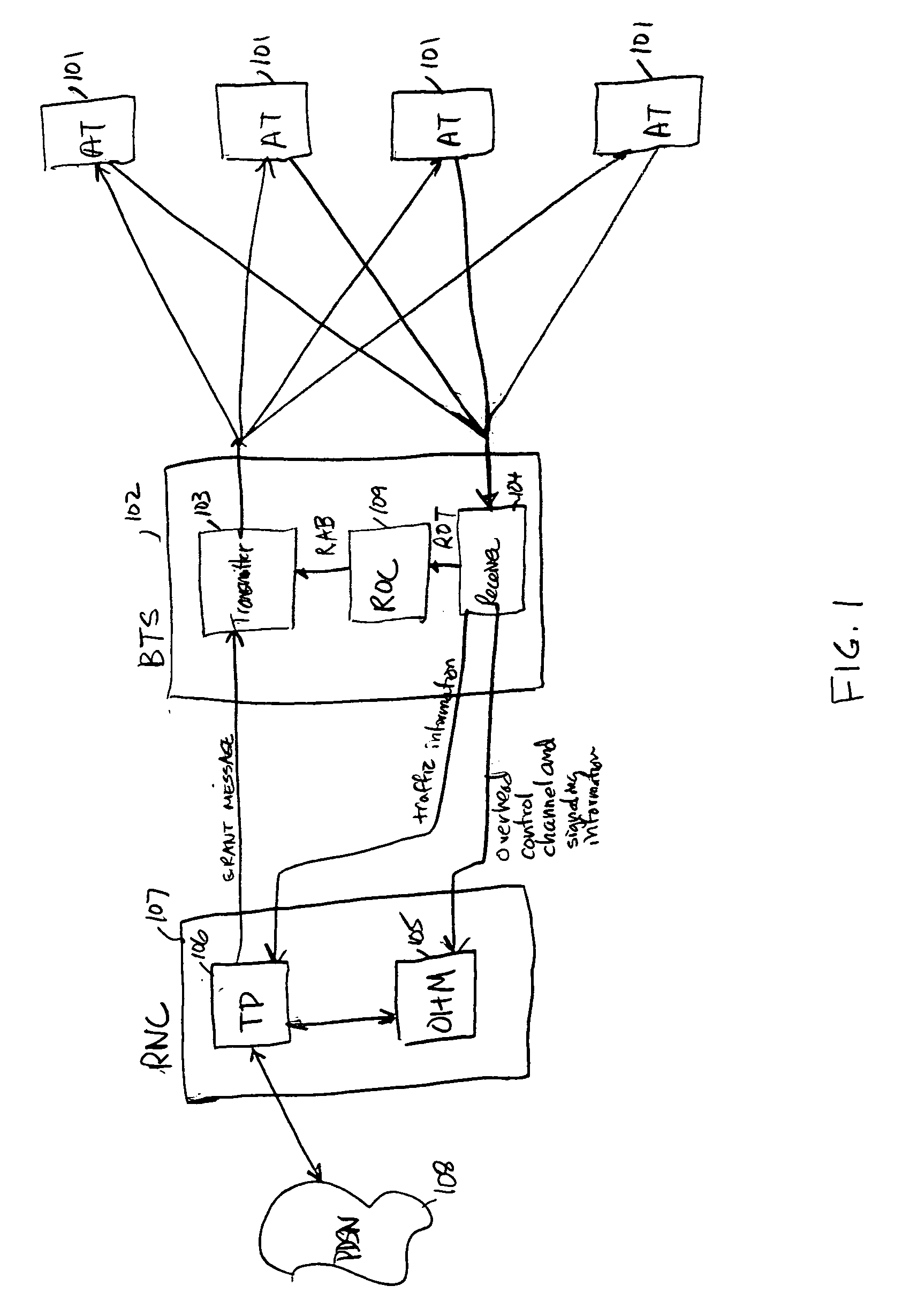
[0014] With reference to FIG. 1, in a prior art wireless communications system 100 in accordance with exemplary CDMA2000 DO Rev A standards, a plurality of ATs 101 have wireless connections established with BTS 102. Transmitter 103 within BTS 102 transmits high-speed data downlink (forward link) to ATs 101 while the ATs transmit high-speed data uplink (reverse link) to receiver 104 within BTS 102. Receiver 104 within BTS 102 sends received overhead control channel information and signaling information to Overhead Manager (OHM) 105 and received traffic information to Traffic Processor (TP) 106 within RNC 107. The traffic information (i.e., high speed data) that TP 106 receives from BTS 102 is sent onto the Public Data Switched Network (PDSN) 108 for transmission to its intended destination, and the traffic information that TP 106 receives from the PDSN 108 that is directed to the ATs currently within the coverage area of BTS 102 is sent to transmitter 103 within BTS 102 for downlink ...


PUM


Abstract

The number of Reverse Activity Bits (RABs) equal to “1” per frame is a Congestion Overload (CO) metric used to determine whether the reverse link in a wireless communications system is in a congestion overload state due to a reverse link RF overload. When the value of the CO metric exceeds a first predetermined threshold that is indicative of a congestion overload condition, the system enters a block state where all new connection requests are blocked. Once in the block state, if the value of the CO metric does not decrease but continues to increase and exceeds a second higher threshold, the system enters a mute state. In the mute state a predetermined large percentage of existing active calls are muted. Specifically, a message is sent downlink to specific ATs instructing them to reduce their transmission rates to zero but to still maintain their active connections.

Description

TECHNICAL FIELD [0001] This invention relates to wireless communications, and more particularly, to controlling congestion on the reverse link in a wireless communications system used for high-speed data applications. BACKGROUND OF THE INVENTION [0002] Wireless communications systems such as those operating in accordance with CDMA2000 DO standards, for example, are optimized for handling high-speed data applications on the reverse link from the mobile terminals (referred to as Access Terminals [ATs] in CDMA2000 DO terminology) to a base station (referred to as a Base Transceiver Station [BTS] in CDMA2000 DO terminology). Unlike other traffic, such as voice, which is continuous in nature, the high-speed data transmitted by an AT is generally discontinuous and bursty. Due to the bursty nature of data calls, a larger number of data calls can be admitted into the system than could be if all ATs were always transmitting simultaneously. With so many data calls involved in established data...

Claims


Application Information

Patent Timeline
IPC IPC(8): H04L12/26H04W28/12H04W28/22
CPCH04W28/22H04W28/12H04W16/04
Inventor YANG, YANGZHU, LILY H.ZOU, JIALIN
Owner RPX CORP
Learn More