Vehicular lighting system

a technology of lighting system and vehicle body, which is applied in the direction of roof, cycle equipment, lighting and heating apparatus, etc., can solve the problems of difficult to distinguish, difficult to easily distinguish, and relative deterioration, so as to achieve enhanced freedom of layout of lighting devices, enhanced degree of front side design, and enhanced effect of evok

Inactive Publication Date: 2006-10-19
HONDA MOTOR CO LTD
View PDF7 Cites 11 Cited by
  • Summary
  • Abstract
  • Description
  • Claims
  • Application Information

AI Technical Summary

Benefits of technology

[0028] According to the fifth through seventh aspects of the invention, in addition to the lighting devices that evoke the image of “eyes”, a second lighting device that evokes the image of a “mouth” is provided, whereby the image of a face can be evoked even more effectively.
[0029] According to the eight aspect of the invention, the pupil portion and the sclera portion can be made to emit light at the same time by means of a simple construction and using the same light source.
[0030] According to the ninth aspect of the invention, a light guide plate for guiding light from a projector type light become unnecessary, whereby the freedom of layout of the lighting devices can be enhanced.
[0031] According to the tenth aspect of the invention, there is no need to separately provide a turn signal, whereby the degree of design of the front side of the vehicle body can be enhanced.
[0032] According to the eleventh and twelfth aspect of the invention, each lighting device can be installed at a position allowing the image of a “face” to be effectively evoked.
[0033] According to the thirteenth aspect of the invention, the line of sight from the “eyes” of the lighting devices faces the front, whereby the recognition of the lighting devices as “eyes” is enhanced so that the image of a “face” can be evoked even more effectively.

Problems solved by technology

Although the above-mentioned techniques exist, the easiest and the most commonly practiced technique for enhancing the visibility of a motorcycle is to perform daytime running of lights, due to problems such as vehicle production cost.
However, there is a fear that the spread of such daytime running of lights to trucks or buses in recent years may cause a relative deterioration in the unique visibility of motorcycles, which has led to a search for lights enabling a further enhancement in visibility.
In this arrangement, however, although the headlight can be associated with “eyes”, it cannot be readily distinguished from other lights.
Although this arrangement allows the headlight to be strongly recognized as “eyes” as compared with the arrangement shown in FIG. 13(a), it is difficult to distinguish between the circular light-emitting portions and the light emitting surfaces corresponding to sclera portions (whites of eyes), so the image as a “face” is formed only to a somewhat greater extent.
In this arrangement, the loss of the contour lines is liable to occur in the nighttime due to the occurrence of glare (a phenomenon whereby an object to be seen becomes hard to see when an extremely bright portion partially exists within the field of view) or changes in the viewing angle.
Further, it is impossible with the conventional headlight arrangement shown in FIG. 12 to evoke the image of a “face” in the nighttime.

Method used


Image

  • Vehicular lighting system
  • Vehicular lighting system
  • Vehicular lighting system

Examples


first embodiment

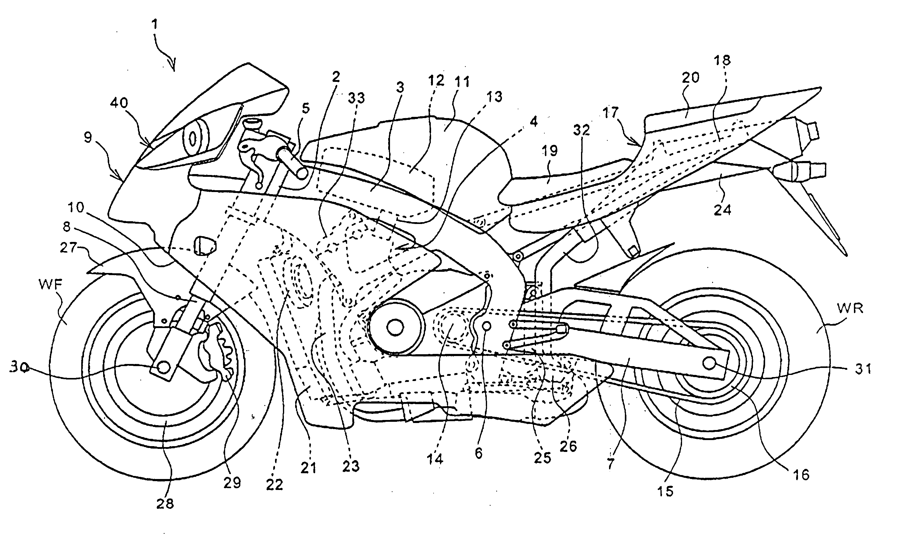
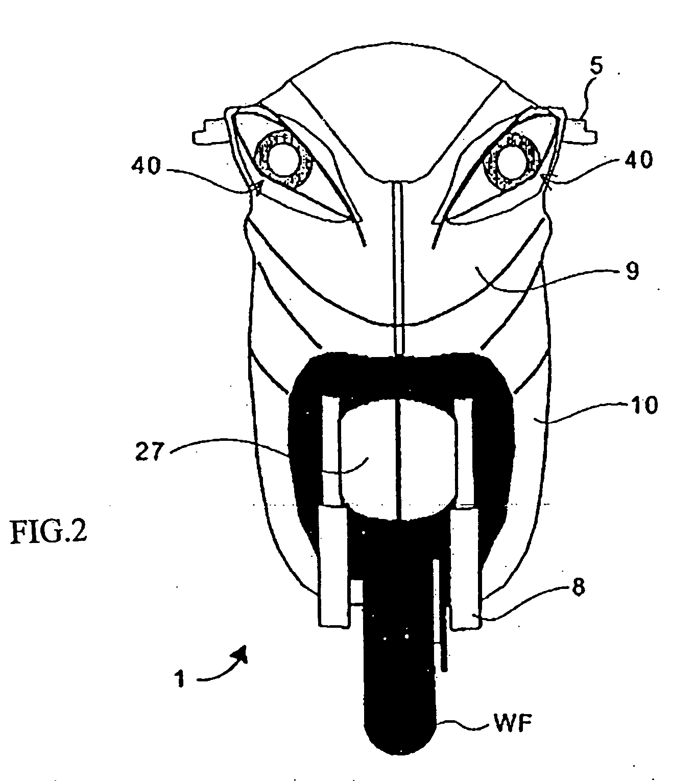
[0055]FIG. 4 are schematic explanatory drawings showing changes in appearance when the lighting locations are varied in the vehicular lighting system according to the present invention as described above. Reference numerals that are the same as those described above denote the same or equivalent portions. As shown in FIGS. 4(a) and 4(b), when the main light 41 and the plates 43a, 43b are lit, it is possible, as described above, to evoke the image of a “face” on the front side of the motorcycle not only under a brightly lit environment such as daytime but also in the nighttime. However, when only the main light 41 and the plate 43b are lit as shown in FIG. 4(c), or when only the main light 41 and the plate 43a are lit as shown in FIG. 4(d), there is a lack of elements constituting “eyes”, causing a marked reduction in the effect of evoking the image of a “face”.

second embodiment

[0056]FIG. 5(a) is a front view of a motorcycle to which a vehicular lighting system according to the present invention is applied. Reference numerals that are the same as those described above denote the same or equivalent portions. In this embodiment, the lighting locations of the headlight 40 are set as the main light 41, and the upper frame 44 and the lower frame 45. As a result, as shown in FIG. 5(b), the contour portions of “eye” emit light, and also the plates 43a, 43b corresponding to “sclera” are dimly lit. The contours of the “eye” and the position of the “pupil” thus become clear, thereby making it possible to effectively evoke the image of a “face” on the front side of the motorcycle even in the nighttime. In contrast, as shown in FIG. 5(c), when only the main light 41 and the plate 43b are lit, and as shown in FIG. 5(d), when only the main light 41 and the plate 43a are lit, there is a lack of elements constituting “eyes”, causing a marked reduction in the effect of evo...

third embodiment

[0057]FIG. 6(a) is a front view of a motorcycle to which a vehicular lighting system according to the present invention is applied. Reference numerals that are the same as those described above denote the same or equivalent portions. In this embodiment, the lighting locations of the head light 40 are set as the ring 42 and the plates 43a, 43b only, and the portion of the main light 41 does not emit light. This arrangement imparts the headlight 40 with the function as a position light. In addition, an underlight 48a functioning as a main headlamp is provided to the upper cowl 9 below the headlights 40. According to the above-described construction, the underlight 48a, which has a configuration in which its both ends are closed in a tapered fashion, can be associated with a “mouth” in addition to the “eyes” of the headlights 40, leading to marked enhancement in the effect of evoking the image of a “face” on the front side of the motorcycle. The underlight 48 preferably has a configura...


PUM


Abstract

A vehicular lighting system that enhances motorcycle visibility is provided. Vehicle front headlights, arranged so as to be laterally symmetrical, are formed in a shape of eyes capable of evoking a face. A headlight includes a circular main light forming a pupil portion, an annular ring forming an iris portion, plates each forming a sclera portion (white of eye), an upper frame forming the contour of an upper eyelid portion, and a lower frame forming the contour of a lower eyelid portion. When the main light and the plates are made to emit light, and the ring is non-light emitting, the pupil portion and the sclera portion are clearly discriminated from each other, thus enabling recognition as “eyes” not only in the daytime but also in the nighttime. The light emitting portions may be set as the main light, the upper frame and the lower frame, and the like.

Description

CROSS-REFERENCE TO RELATED APPLICATIONS [0001] The present invention claims priority under 35 USC 119 based on Japanese patent application No. 2005-119789, filed on Apr. 18, 2005. The subject matter of this priority document is incorporated by reference herein. BACKGROUND OF THE INVENTION [0002] 1. Field of the Invention [0003] The present invention relates to a vehicular lighting system, and more specifically to a vehicular lighting system for evoking an image of a “face” by having each lighting device recognized as an “eye”. [0004] 2. Description of the Background Art [0005] Conventionally, efforts have been made to develop a technique for enhancing the visibility of a motorcycle. JP-A No. 334976 / 2001 below discloses lamp devices for visual recognition which are additionally provided to a head lamp normally equipped to a motorcycle. The lamp device are adapted to emit light different from that of the head lamp by methods such as flashing blue or green light or diffusing light to t...

Claims


Application Information

Patent Timeline
Patent Type & Authority Applications(United States)
IPC IPC(8): B60Q1/00
CPCB60Q1/0052B62J6/02B62J6/005B60Q1/0035B62J6/026B62J6/055
Inventor KUSHIDA, KAZUMITSUMATSUMOTO, YOSHIYUKIMURATA, YUTAKA
Owner HONDA MOTOR CO LTD
Why Eureka
Try Eureka