
Optical scanning apparatus and image forming apparatus

a technology of optical scanning and image forming, which is applied in the field of image forming apparatuses and optical scanning apparatuses, can solve the problems of deterioration of image quality, low productivity, and high cost, and achieve the effect of maintaining a long time-consuming and stable registration accuracy of each station

Inactive Publication Date: 2006-10-19
RICOH KK
View PDF6 Cites 29 Cited by
  • Summary
  • Abstract
  • Description
  • Claims
  • Application Information

AI Technical Summary

Benefits of technology

[0015] It is a general object of the present invention to provide an improved and useful optical scanning apparatus used in an image forming apparatus in which the above-mentioned problems are eliminated.
[0016] A more specific object of the present invention is to provide an image forming apparatus and an optical scanning apparatus used in such an image forming apparatus, which can perform formation and recording of a high-quality image including a color image without a color shift and color change by stably maintaining a registration accuracy of each station for a long time.

Problems solved by technology

Accordingly, in a multiple-color image forming apparatus in which a plurality of photosensitive drums are arranged in a direction of conveying a transfer medium so as to overlap toner images formed by image forming stations of each color, unless an irradiating position of a light beam on each of the photosensitive drums is accurately aligned, a color shift or a color change may be generated, which causes deterioration of image quality.
However, there is a problem in that productivity is low and a cost is high since it takes time and labor to machine receiving surfaces of component parts.
However, the plastic housing is inferior to a metal housing in reliability over a long time.
Accordingly, an irradiating position on each of the photosensitive drums is displaced and a time taken from an irradiating position to a transfer position in each station, which causes a problem of occurrence of a registration displacement.
Thus, during such a time period, it is set to a recording unable state, which elongates print wait time and results in deterioration in operation.
Additionally, if a number of corrections is increased, an amount of consumption of the waist toner is increased.
Especially, if a distance between the stations is increased, the housing is enlarged due to thermal expansion, and, thereby, a warp tends to be generated in the housing, which results in difficulty in acquiring dimensional stability.
Additionally, since a thickness is increased inevitably and a mixing ratio of glass fibers is increased, productivity is deteriorated and a cost is increased even if a plastic material is used.
However, if an entire housing is made of a metal sheet, the configuration of the metal housing becomes complex to support a plurality of light sources and scanning lenses of the plurality of stations.
Thus, there is a problem in that a number of fabrication processes is increased and assembling becomes troublesome, which results in an increase in cost.
However, there is a problem in that a positional accuracy cannot be maintained due to a stress applied to the framed is the installation surface of the apparatus body is not flat.

Method used


Image

  • Optical scanning apparatus and image forming apparatus
  • Optical scanning apparatus and image forming apparatus
  • Optical scanning apparatus and image forming apparatus

Examples


first embodiment

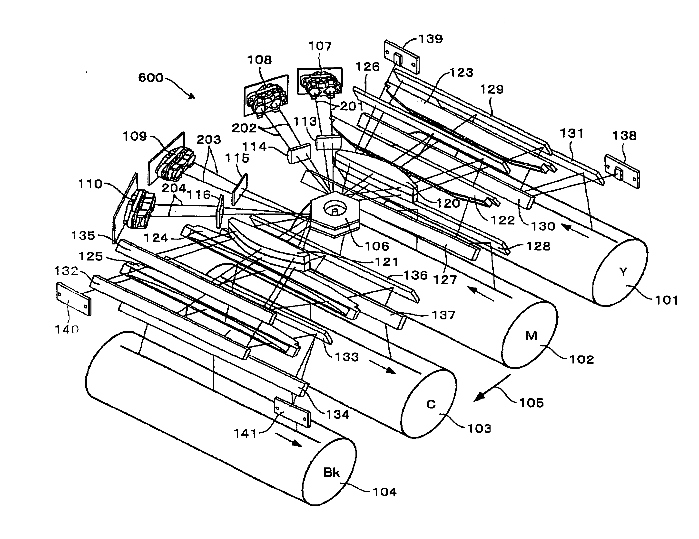
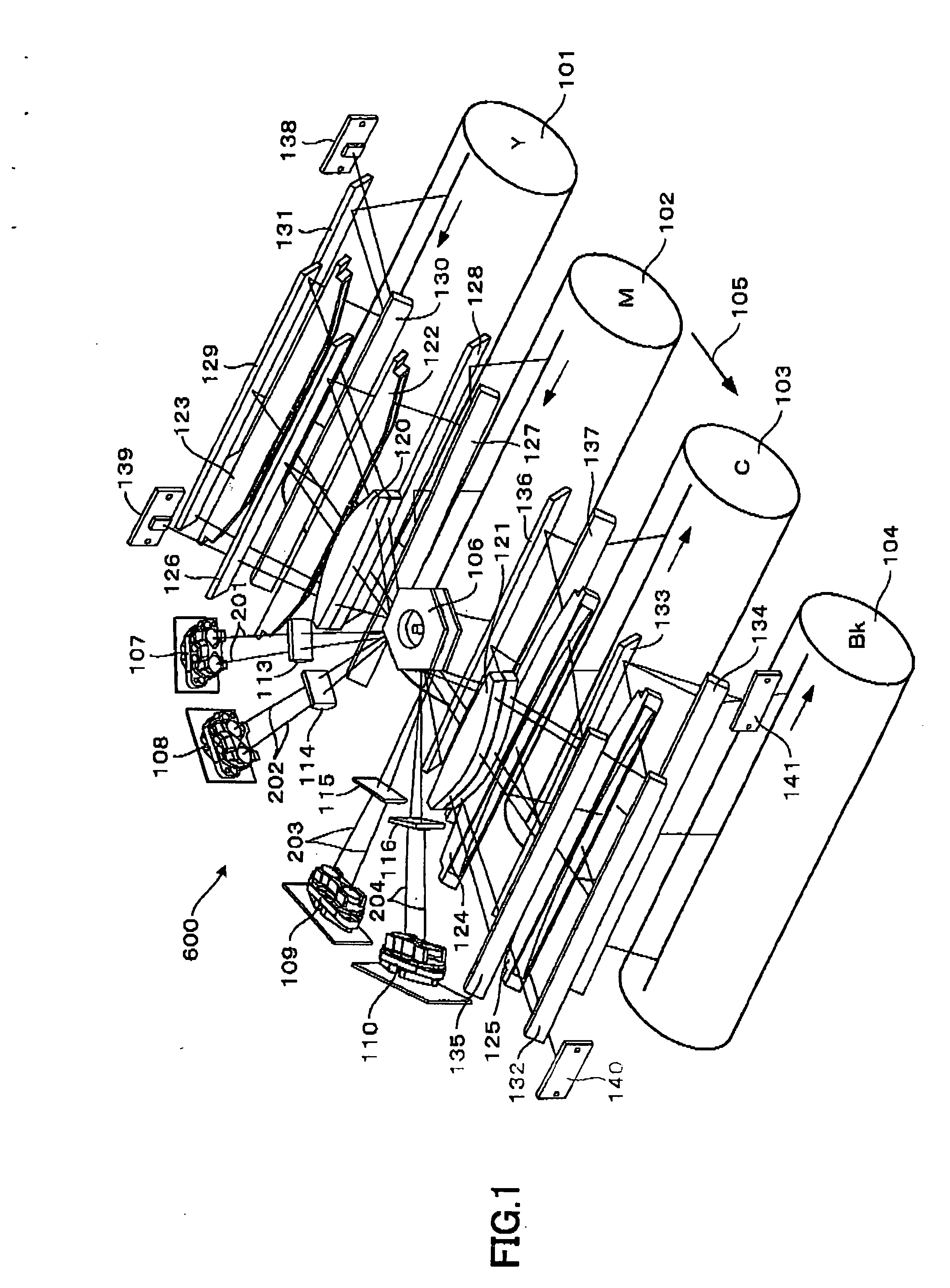
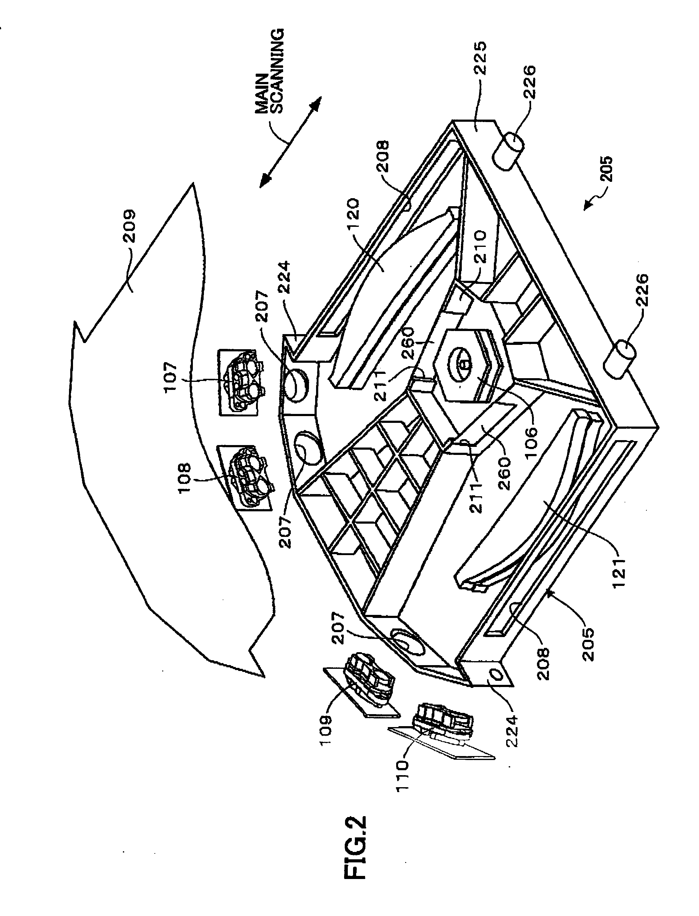
[0049] A description will now be given, with reference to FIGS. 1 through 12, of a first embodiment of the present invention.

[0050] First, a description will be given, with reference to FIG. 12, of an outline structure of a color image forming apparatus 620 equipped with an optical scanning apparatus 600.

[0051] The color image forming apparatus 620 comprises an intermediate transfer belt 606 as an intermediate transfer member. A plurality of image forming stations are arranged along a direction of movement of the intermediate transfer belt 606. The image forming stations includes photosensitive drums 101, 102, 103 and 104 as image carriers, respectively.

[0052] A yellow (Y) toner image is formed in the image forming station having the photosensitive drum 101. A magenta (M) toner image is formed in the image forming station having the photosensitive drum 102. A cyan (C) toner image is formed in the image forming station having the photosensitive drum 103. A black (Bk) toner image i...

second embodiment

[0128] A description will be given, with reference to FIGS. 13 through 16, of a second embodiment of the present invention.

[0129] The second embodiment differs from the first embodiment only in that a color image forming apparatus 720 equipped with an optical scanning apparatus 700 is provided instead of the color image forming apparatus 620 equipped with the optical scanning apparatus 600.

[0130] The color image forming apparatus 720 differs from the color image forming apparatus 620 in that the optical scanning apparatus 700 is provided instead of the optical scanning apparatus 600. Thus, the color image forming apparatus 720 according to the second embodiment has the same structure and operation as the color image forming apparatus 620 according to the first embodiment except for the optical scanning apparatus. Accordingly, a description will be given below, with reference to FIG. 13 through FIG. 16, of a structure and an operation of the optical scanning apparatus, which differ...


PUM


Abstract

An optical scanning apparatus includes a housing that positions and holds a plurality of light sources emitting light beams, a deflection mirror that deflects the light beams to perform main scanning, and at least one of optical image forming elements closest to the deflection mirror to form images on respective image carriers. A plurality of reflectors guide the light beams exiting the housing to the respective image carriers. A pair of support members face each other to support the housing in a main scanning direction. A support mechanism supports the reflectors by bridging the reflectors between the support members and also couples the support members to each other. Relative positions of the reflectors are arranged in a cross-sectional plane perpendicular to a main scanning direction between the support members.

Description

BACKGROUND OF THE INVENTION [0001] 1. Field of the Invention [0002] The present invention generally relates to image forming apparatuses and optical scanning apparatuses and, more particularly, to an image forming apparatus such as a copy machine, a printer, a facsimile machine, a plotter or a combination machine of the aforementioned and an optical scanning apparatus used in such an image forming apparatus. [0003] 2. Description of the Related Art [0004] In an image forming apparatus using a Carlzon process, latent-image formation, development and transfer are performed in association with rotation of a photosensitive drum. Accordingly, in a multiple-color image forming apparatus in which a plurality of photosensitive drums are arranged in a direction of conveying a transfer medium so as to overlap toner images formed by image forming stations of each color, unless an irradiating position of a light beam on each of the photosensitive drums is accurately aligned, a color shift or a ...

Claims


Application Information

Patent Timeline
IPC IPC(8): G02B26/08
CPCG02B26/123
Inventor NAKAJIMA, TOMOHIRO
Owner RICOH KK
Learn More