
Autofocus device and method

a technology of autofocus and distance measurement, which is applied in the direction of camera focusing arrangement, printers, instruments, etc., can solve the problems of difficult to measure the distance to the subject, and the difficulty of carrying out an autofocus operation using the measured distance, so as to increase the distance measurement accuracy

Inactive Publication Date: 2006-10-19
SONY CORP
View PDF4 Cites 19 Cited by
  • Summary
  • Abstract
  • Description
  • Claims
  • Application Information

AI Technical Summary

Benefits of technology

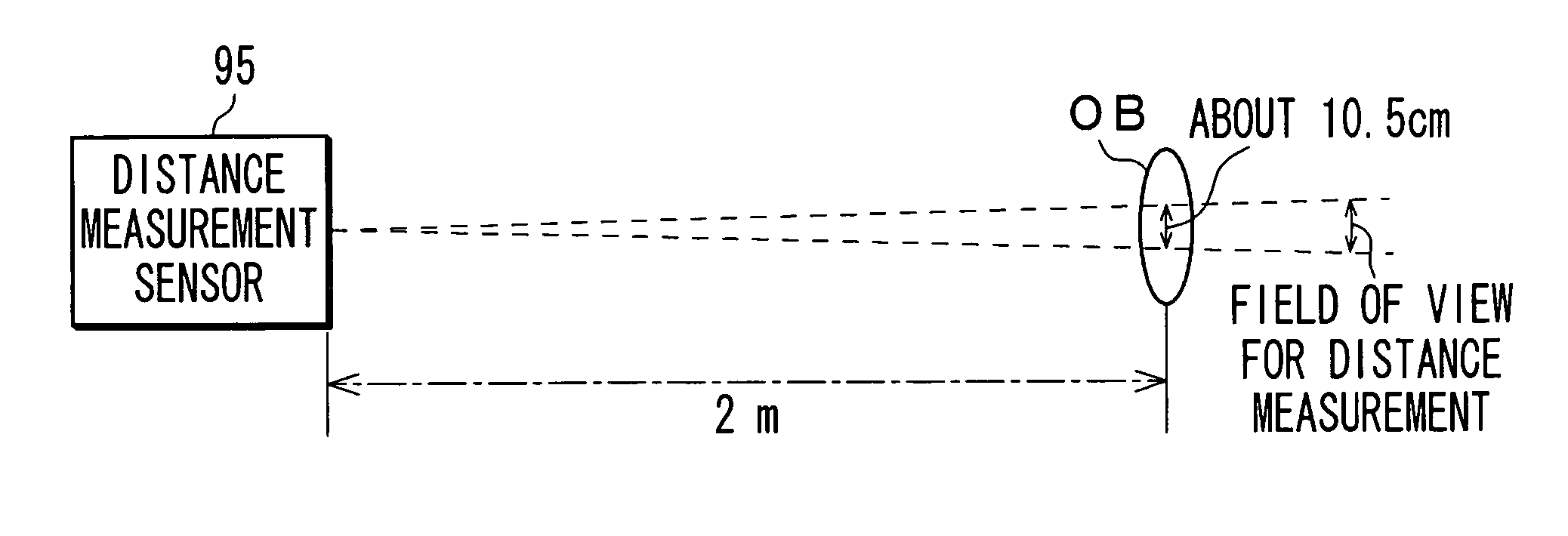
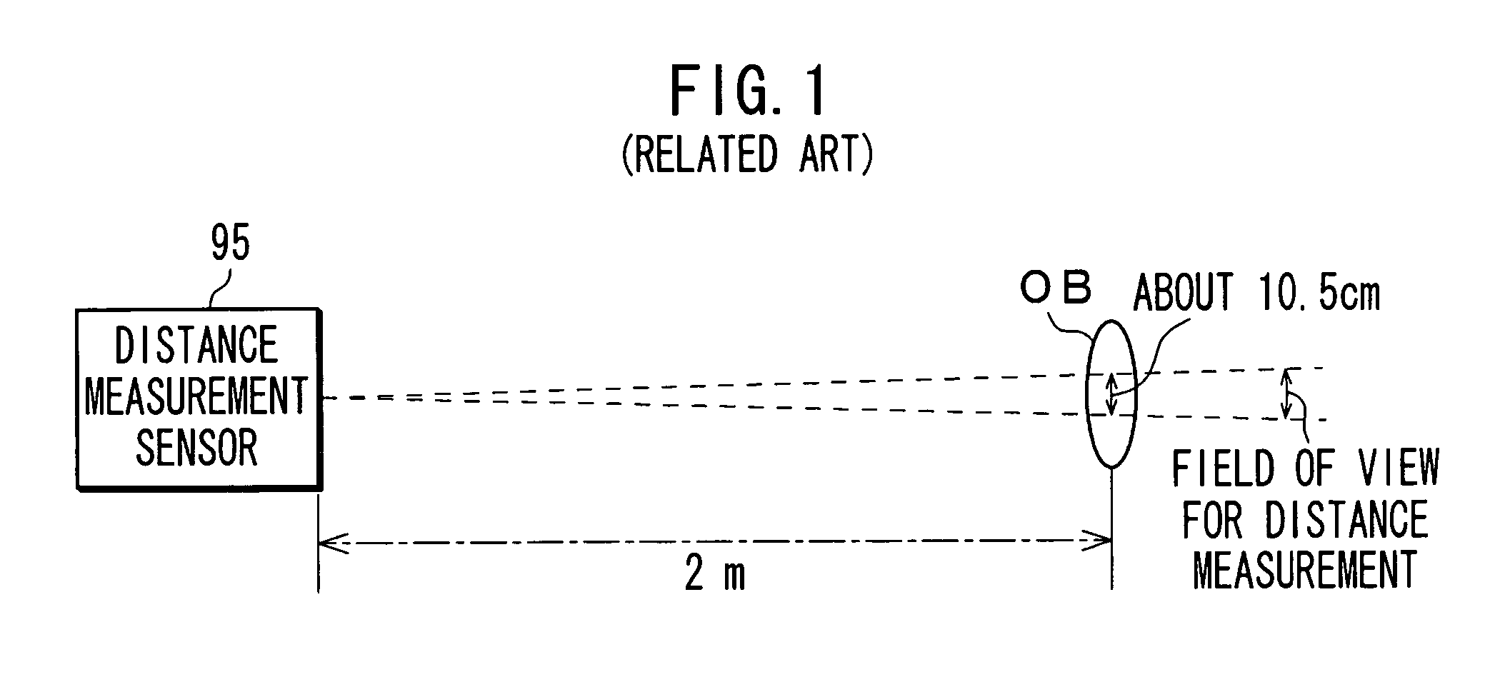
[0006] If decreasing a field of view for distance measurement to concentrate a narrower distance measurement area when the focus adjustment operation using a measured distance result that indicates a distance to a desired subject is done, it is possible to focus on the subject correctly by imaging the subject with it being put in the distance measurement area. If an image of the subject is imaged smaller because the long distance to the subject exists, it is possible to increase distance measurement accuracy because any influence by a background is reduced when decreasing the field of view for distance measurement to concentrate a narrower distance measurement area.
[0008] It is desirable to present autofocus device and method and a program product therefor that can focus on a desired subject automatically using measured distance results to the desired subject by enhancing distance measurement performance.
[0009] According to an embodiment of the present invention, there is provided an autofocus device having a lens-driving unit that drives a lens, a focal-point-position-detecting unit that detects a position of a focal point of the lens, and a distance measurement sensor that measures a distance to a subject based on each of the fields of view for distance measurement. In the distance measurement sensor, a reference field of view for distance measurement and any one of a field of view for distance measurement being offset outwardly from the reference field of view for distance measurement and a field of view for distance measurement having a field of view that is different from the reference field of view for distance measurement are provided. The device also has a control unit that performs a focusing operation to control the lens-driving unit to drive the lens, thereby meeting the position of the focal point of the lens detected by the focal-point-position-detecting unit to an in-focus position thereof. The control unit allows the focusing operation to start by setting the lens drive based on a representative value that is selected from measured distance results obtained by the distance measurement sensor and the position of the focal point of the lens detected by the focal-point-position-detecting unit.
[0013] Thus, according to any embodiments of the invention, the representative value is selected from the measured distance results obtained by the distance measurement using plural fields of view for distance measurement and a lens drive is set based on this representative value and the detected position of the focal point of the lens, thereby starting the focusing operation. Thus, if it fails to get a correct measured distance result even when using the reference field of view for distance measurement, a field of view for distance measurement being offset outwardly from the reference field of view for distance measurement and / or a field of view for distance measurement having a field of view that is different from the reference field of view for distance measurement can be used to obtain measured distance results. By selecting and using the representative value from the measured distance results obtained by using these fields of view for distance measurement, the lens drive is set to start the focusing operation. Thus, it is possible to focus on a desired subject automatically using the measured distance results to the desired subject by enhancing distance measurement performance of the distance measurement sensor.

Problems solved by technology

Thus, if the distance measurement is carried out using any difference in contracts of the subject and a person OB who wears a plain sweater without a pattern is imaged, it is difficult to measure a distance to the subject because there is no difference in contracts of the subject within the distance measurement area.
This results in difficulty of carrying out an autofocus operation using the measured distance result.

Method used


Image

  • Autofocus device and method
  • Autofocus device and method
  • Autofocus device and method

Examples


Embodiment Construction

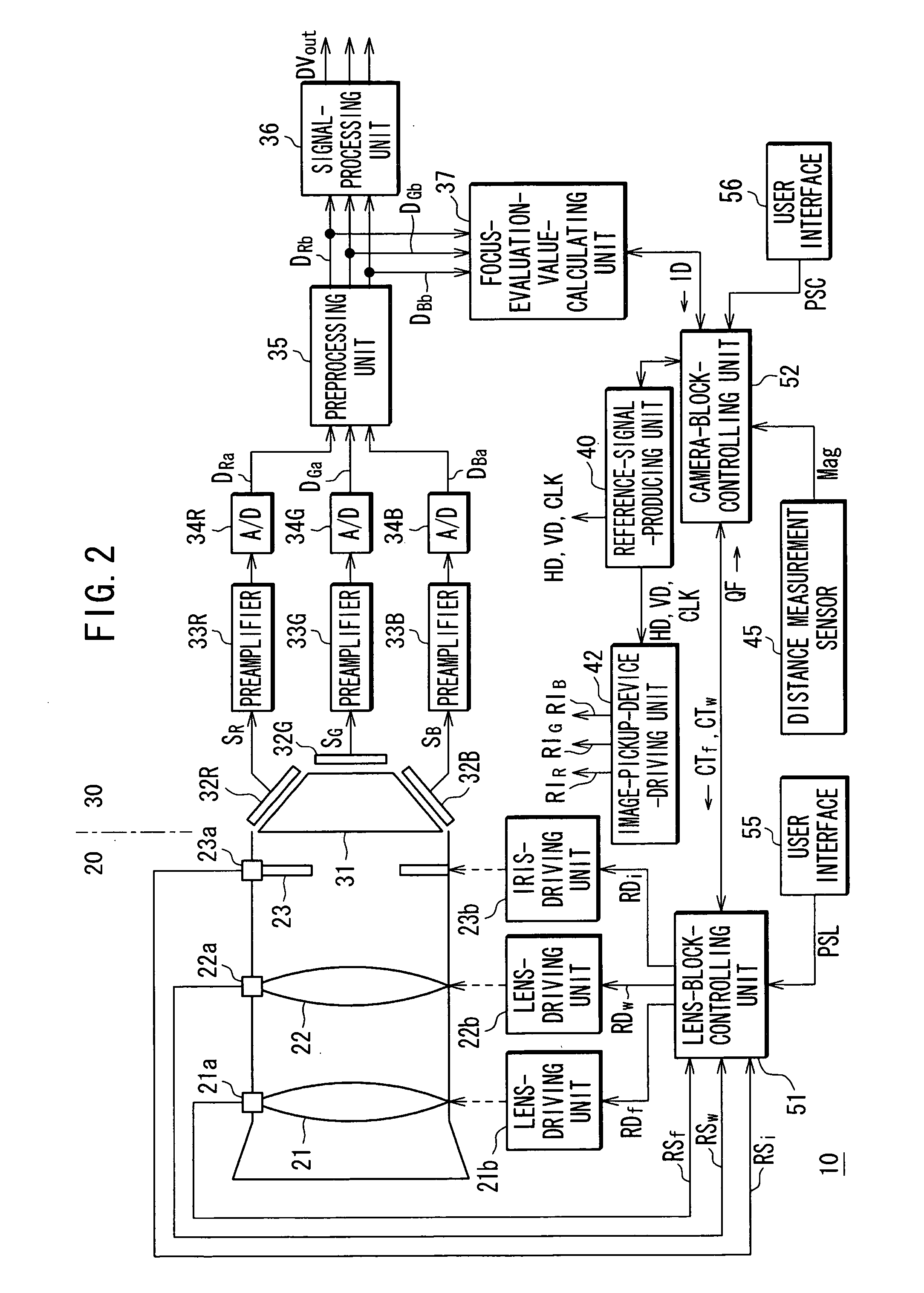
[0028] The following will describe embodiments of the invention with reference to the accompanying drawings. FIG. 2 shows a whole configuration of an imaging apparatus such as a video camera 10 having an autofocus mechanism.

[0029] A lens block 20 of the video camera 10 is constituted of an imaging lens, a lens-position-detecting unit that detects a position of the imaging lens, lens-driving unit that drives the imaging lens and the like. It is to be noted that in the lens block 20 shown in FIG. 2, as the imaging lens, a focus lens 21 for focusing an image of subject on an imaging surface of an imaging element and a wobbling lens 22 for utilizing determination of a driving direction of the focus lens 21 to meet a position of its focal point to an in-focus position are illustrated.

[0030] For the focus lens 21, are provided a lens-position-detecting unit 21a that detects a position of the focus lens 21, i.e. a focal-point-position-detecting unit that detects a position of a focal poi...


PUM


Abstract

Autofocus device has a lens-driving unit, a focal-point-position-detecting unit that detects a position of a focal point of the lens, and a distance measurement sensor. The sensor measures a distance to a subject based on a reference field of view for distance measurement and a field of view for distance measurement being offset outwardly from the reference field of view and / or a field of view for distance measurement having a field of view that is different from the reference field of view. The device has a control unit that controls the lens-driving unit to drive the lens to meet the position of the focal point of the lens to an in-focus position thereof. The focusing operation starts by setting the lens drive based on a representative value selected from measured distance results obtained by the distance measurement sensor and the position of the focal point of the lens.

Description

CROSS REFERENCE TO RELATED APPLICATION [0001] The present invention contains subject matter related to Japanese Patent Application No. JP2005-119038 filed in the Japanese Patent Office on Apr. 15, 2005, the entire contents of which being incorporated herein by reference. BACKGROUND OF THE INVENTION [0002] 1. Field of the Invention [0003] This invention relates to autofocus device and method and a program product therefor, which are used in an imaging apparatus such as a video camera and a digital still camera. [0004] 2. Description of Related Art [0005] The imaging apparatus such as a video camera and a digital still camera has been equipped with any autofocus mechanism that automatically focuses on a subject. The autofocus mechanism adds frequency components of an image signal in a particular region that is provided in an imaging frame (finder's view) to calculate a focus evaluation value thereof and drives a focus lens so that the maximum focus evaluation value can be given (see J...

Claims


Application Information

Patent Timeline
Patent Type & Authority Applications(United States)
IPC IPC(8): G03B13/00
CPCG02B7/38H04N5/23212G03B13/36H04N23/671H04N23/673
Inventor ITO, YUJIROSUTO, HIDEKAZUTAKEMOTO, SHINJI
Owner SONY CORP
Learn More