
Radio receiver

a radio receiver and receiver technology, applied in the field of radio receivers, can solve the problems of reducing the number of radio receivers, consuming a large amount of electrical power from the aircraft, and reducing the weight of the aircraft, so as to reduce the weight and power consumption, safe operation of the aircraft, and free up the airframe space

Inactive Publication Date: 2006-10-12
HONEYWELL INT INC
View PDF54 Cites 23 Cited by
  • Summary
  • Abstract
  • Description
  • Claims
  • Application Information

AI Technical Summary

Benefits of technology

[0009] The present invention is directed to a radio receiver that is operable to receive one or more radio frequency bands containing a plurality of information channels using various modulation and encoding schemes, digitize the plurality of received channels using a single analog to digital converter, digitally select and decode one or more of the plurality of digitized channels, and generate one or more output signals that correspond to one or more of the plurality of digitized channels. The radio receiver may be used to replace multiple conventional aviation radio receivers to thereby free up airframe space and reduce weight and power consumption, while still allowing a flight crew to receive all of the radio signal broadcasts required to safely operate an aircraft.

Problems solved by technology

There are a number of disadvantages associated with carrying multiple radio receivers (each of which is limited to one channel of information) in the cockpit of an aircraft.
For example, the radio receivers needed to pilot an aircraft (each of which is often housed within a separate enclosure or case) occupy valuable airframe space.
Also, the sheer number of radio receivers adds weight to the aircraft.
In addition, the radio receivers together consume a large amount of electrical power from the aircraft.
Other disadvantages should be apparent to those skilled in the art.

Method used


Image

  • Radio receiver
  • Radio receiver
  • Radio receiver

Examples


first exemplary embodiment

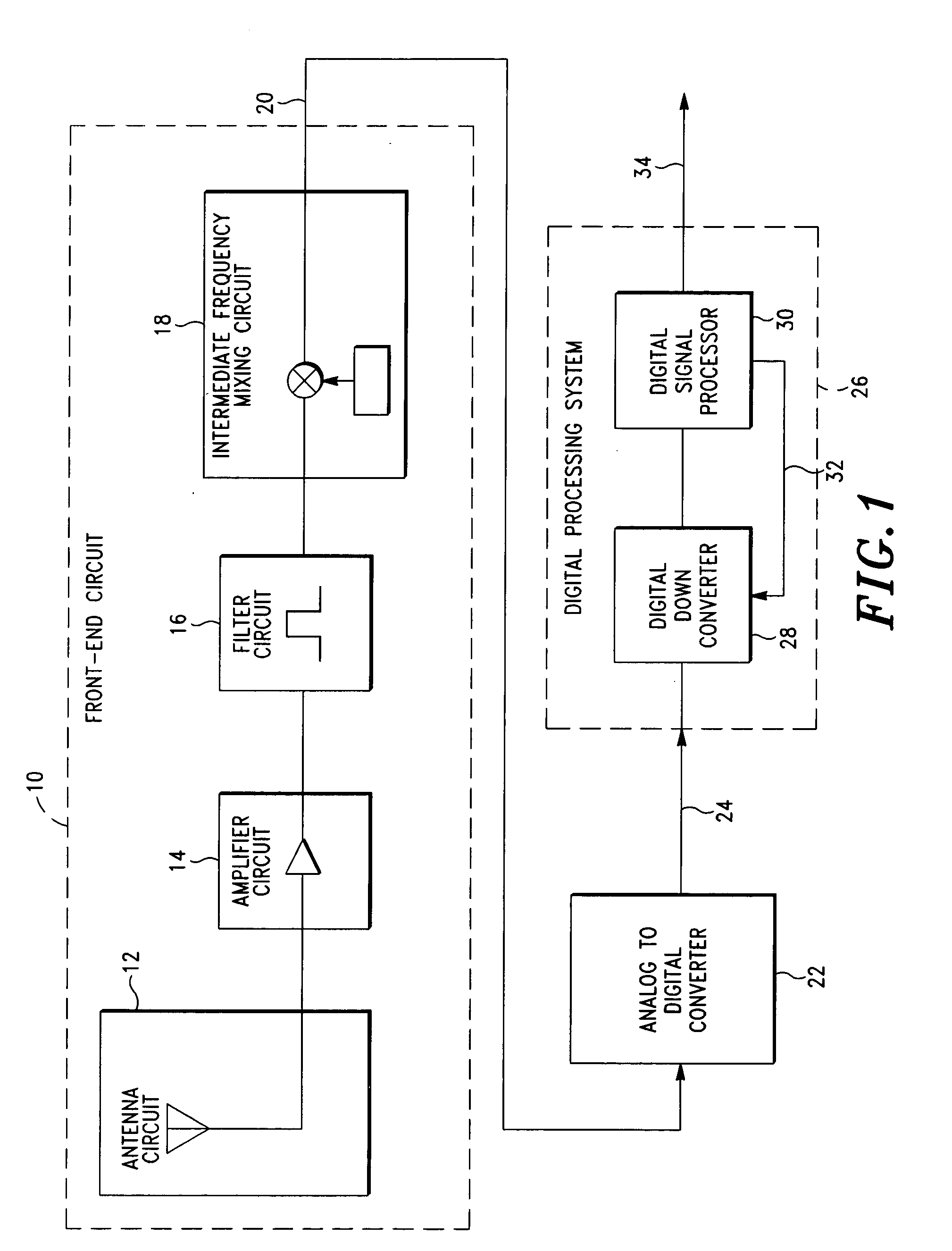
[0022] Referring to FIG. 1, a radio receiver in accordance with a first exemplary embodiment of the present invention includes a front-end circuit 10 (which generally comprises an antenna circuit 12, an amplifier circuit 14, a filter circuit 16 and an intermediate frequency mixing circuit 18), an analog to digital converter 22, and a digital processing system 26 (which generally comprises a digital down converter 28 and a digital signal processor 30). As will be described in greater detail hereinbelow, front-end circuit 10 receives a plurality of radio signals transmitted across a frequency band and generates an analog signal 20 corresponding to a plurality of channels within that frequency band. Analog to digital converter 22 converts analog signal 20 into a digital signal 24 to thereby digitize the received radio signals. Digital signal 24 is then processed by digital processing system 26, which generates an output signal 34 corresponding to at least one of the digitized channels ...

second exemplary embodiment

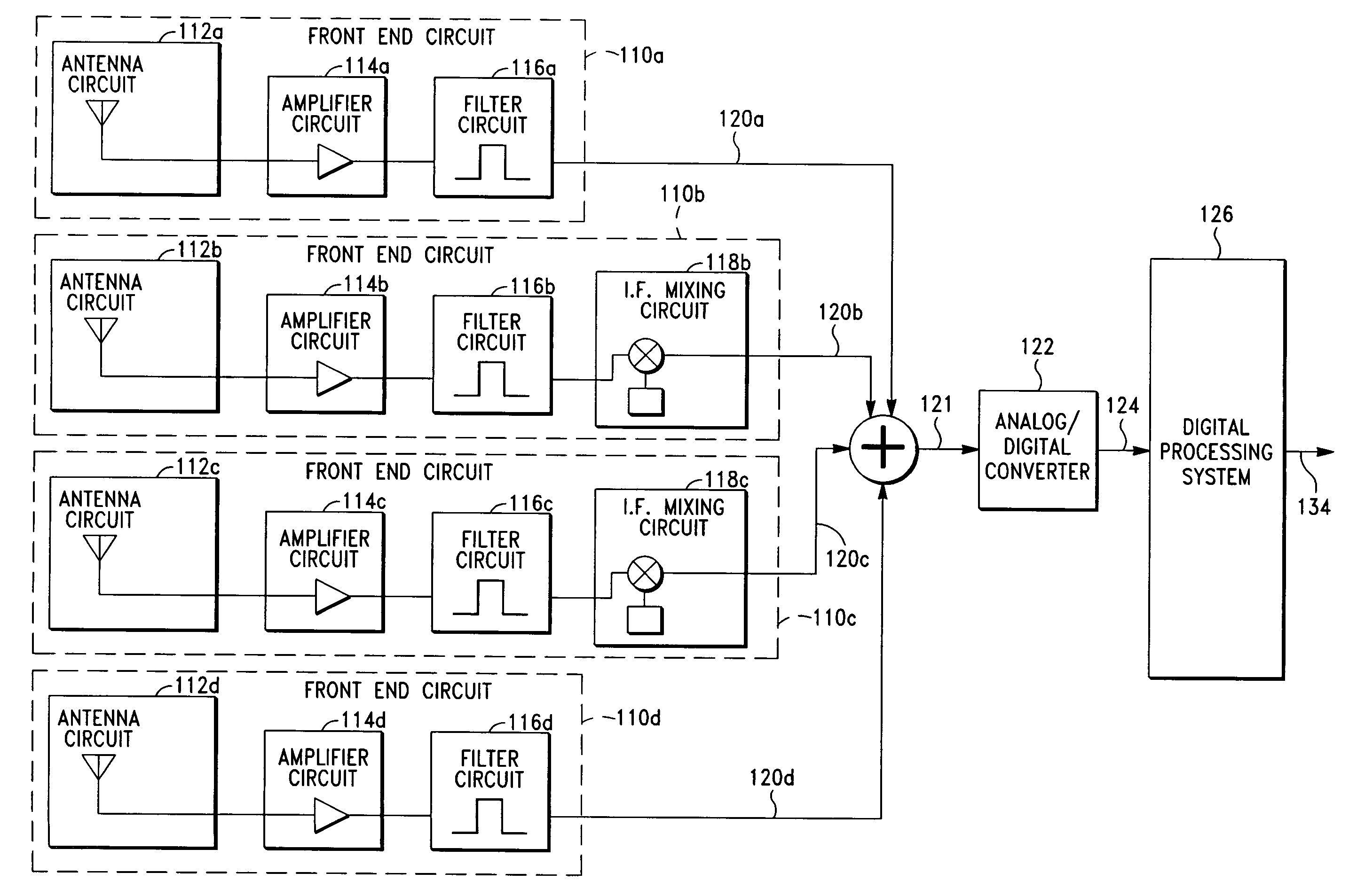
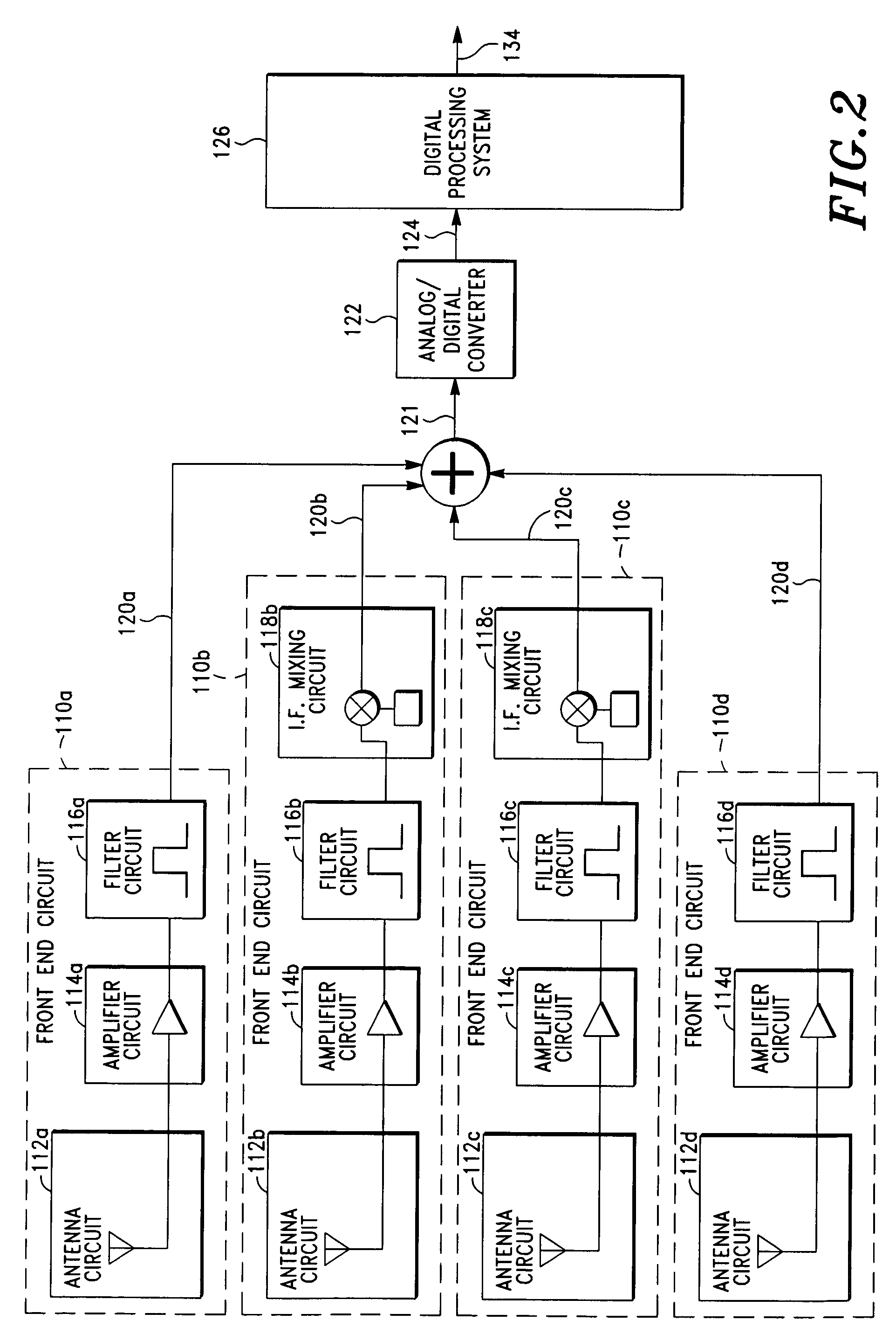
[0040] Turning now to FIG. 2, a radio receiver in accordance with a second exemplary embodiment of the present invention includes a plurality of front-end circuits 110a, 110b, 110c, 110d (each of which is configured in accordance with the description of front-end circuit 10 of the first exemplary embodiment), an analog to digital converter 122 (which is configured in accordance with the description of analog to digital converter 22 of the first exemplary embodiment), and a digital processing system 126 (which is configured in accordance with the description of digital processing system 26 of the first exemplary embodiment).

[0041] As can be seen, front-end circuit 110a includes an antenna circuit 112a, an amplifier circuit 114a and a filter circuit 116a (but no intermediate frequency circuit); front-end circuit 112b includes an antenna circuit 112b, an amplifier circuit 114b, a filter circuit 116b and an intermediate frequency mixing circuit 118b; front-end circuit 112c includes an ...

third exemplary embodiment

[0047] Turning next to FIG. 3, a radio receiver in a accordance with a third exemplary embodiment of the present invention includes two front-end circuit groups 211a, 211b. Front-end circuit group 211a includes a plurality of front-end circuits 210a, 210b and front-end circuit group 211b includes a plurality of front-end circuits 210c, 210d (wherein each of the front-end circuits is configured in accordance with the description of front-end circuit 10 of the first exemplary embodiment). The radio receiver also includes a plurality of analog to digital converters 222a, 222b (each of which is configured in accordance with the description of analog to digital converter 22 of the first exemplary embodiment), and a digital processing system 226 (which is configured in accordance with the description of digital processing system 26 of the first exemplary embodiment).

[0048] Within front-end circuit group 211a, front-end circuit 210a includes an antenna circuit 212a, an amplifier circuit 2...


PUM


Abstract

A radio receiver is provided that includes a front-end circuit operable to receive radio signals transmitted across a frequency band and generate an analog signal corresponding to a plurality of channels within the frequency band. Also included is an analog to digital converter operable to convert the analog signal to a digital signal, and a digital processing system operable to process the digital signal and simultaneously generate one or more output signals corresponding to at least one of the plurality of channels within the frequency band. Various exemplary embodiments of the radio receiver and associated method are provided.

Description

CROSS-REFERENCE TO RELATED APPLICATIONS [0001] Not Applicable. STATEMENT REGARDING FEDERALLY SPONSORED RESEARCH OR DEVELOPMENT [0002] Not Applicable BACKGROUND OF THE INVENTION [0003] 1. Field of the Invention [0004] The present invention relates to radio receivers, and more particularly to broadband radio receivers used for aviation communications and navigation. [0005] 2. Description of Related Art [0006] Aviation communications and navigation relies heavily on radio signal broadcasts to provide critical information to those involved in piloting and controlling aircraft. Pilots use various types of radio receivers and instruments carried on an aircraft to communicate with ground controllers, air traffic controllers, and pilots of other aircraft, as well as to receive all of the radio signal broadcasts required to safely operate the aircraft. For example, some radio receivers may be used to receive broadcast navigation signals to determine aircraft position and course. Other radio ...

Claims


Application Information

Patent Timeline
IPC IPC(8): H04L27/00G01S3/04H04B1/28
CPCG01S3/043H04B1/28H04B1/0007H04B1/0003
Inventor GIBSON, TIMOTHY P.HUNTER, JEFFREY K.RICHEY, MANUEL F.TRIPLETT, GREGORY L.
Owner HONEYWELL INT INC
Learn More