
Method of operating a passive optical network

Active Publication Date: 2006-10-05
WSOU INVESTMENTS LLC
View PDF8 Cites 0 Cited by
  • Summary
  • Abstract
  • Description
  • Claims
  • Application Information

AI Technical Summary

Benefits of technology

[0009] On one hand, if the transmission quality of the link proves to be better, it is possible to increase the number of signal states of the optical signal. Due to the better transmission quality, the optical line termination and/or the corresponding network termination is able to distinguish this increased number of signal states cor

Problems solved by technology

However, the transmission qualities of the links between the optical line termination and the network terminations may be different or may even change from time to time.
For example, changes within the passive optical fiber network ma

Method used


Image

  • Method of operating a passive optical network
  • Method of operating a passive optical network
  • Method of operating a passive optical network

Examples


Example

DETAILED DESCRIPTIONS OF THE DRAWINGS

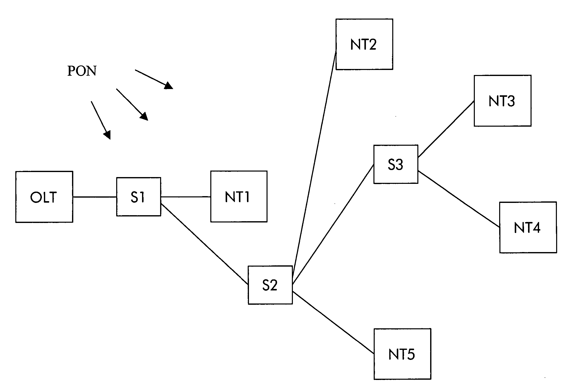
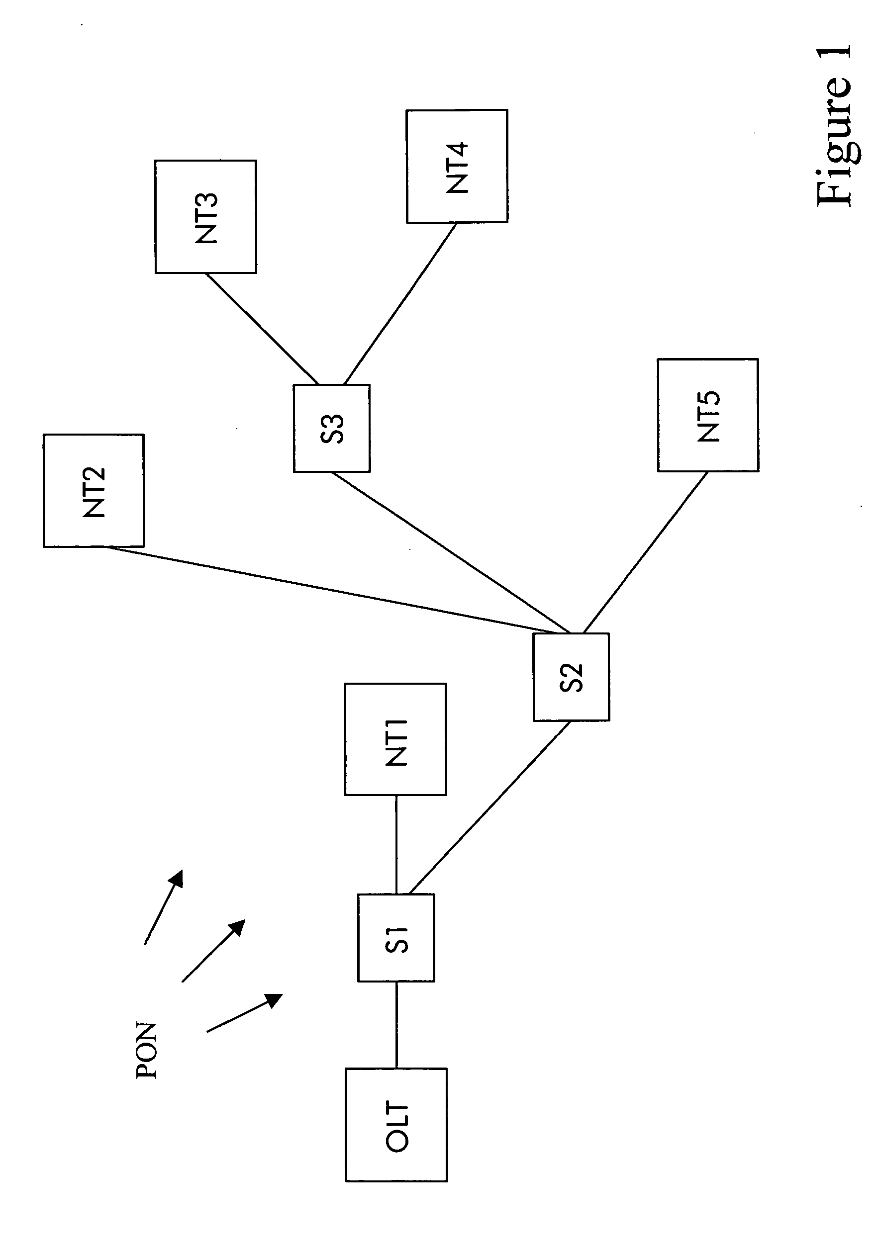
[0022] According to FIG. 1, the optical line termination OLT is connected with the first network termination NT1 by optical fibers via a first optical splitter S1. The first optical splitter S1 is connected by an optical fiber with a second optical splitter S2 which, in turn, is connected by an optical fiber with a third optical splitter S3. The second and the fifth network termination NT2, NT5, are connected with the second optical splitter S2 and the third and the fourth network termination NT3, NT4 are connected with the third optical splitter S3.

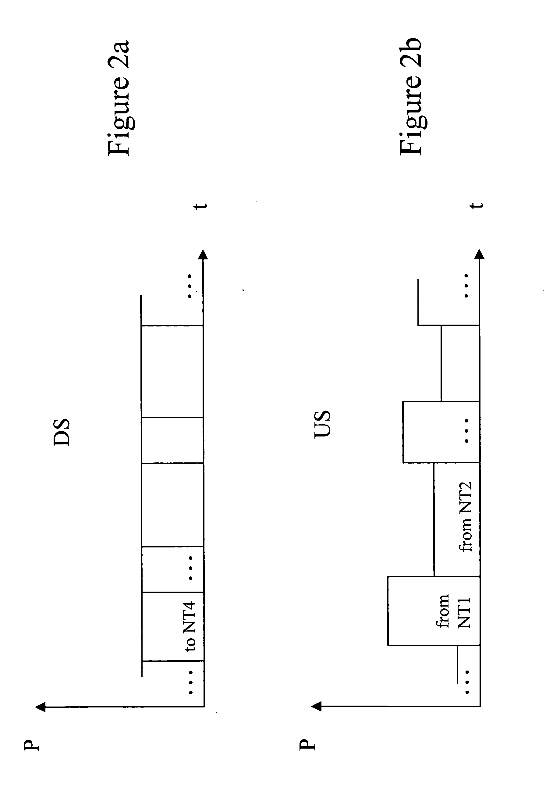
[0023] The transmission direction from the optical line termination OLT to the network terminations NT1, NT2, NT3, NT4, NT5 is called downstream. The opposite direction, i.e. the direction from the network terminations NT1, NT2, NT3, NT4, NT5 to the optical line termination OLT is called upstream.

[0024] The optical paths may be realized on a single fiber for combined upstream and downstream directi...


PUM


Abstract

The invention relates to a method of operating a passive optical network. The passive optical network comprises an optical line termination being connected via optical fibers to a number of network terminations. The method comprises the step of generating an optical signal to be transmitted on one of the optical fibers comprising a number of signal states. The method is characterized in that the number of signal states is changed.

Description

BACKGROUND OF THE INVENTION [0001] The invention is based on a priority application EP05290737.5 which is hereby incorporated by reference. [0002] The invention relates to a method of operating a passive optical network comprising an optical line termination being connected via optical fibers to a number of network terminations and comprising the step of generating an optical signal to be transmitted on one of the optical fibers comprising a number of signal states. The invention also relates to a corresponding passive optical network, to a corresponding optical line termination and to a corresponding network termination. [0003] It is known to define the transmission rate within a passive optical network to a pre-defined value. Under this condition, all network terminations are able to communicate with the optical line termination. [0004] In order to incorporate network terminations in the passive optical network that have a higher transmission rate, it is known to use several diffe...

Claims


Application Information

Patent Timeline
IPC IPC(8): H04B10/20H04B10/27
CPCH04B10/27H04B10/25H04J14/00H04B10/07
Inventor KRIMMEL, HEINZ-GEORG
Owner WSOU INVESTMENTS LLC
Learn More