Magnetron

a technology of magnets and shields, applied in the field of magnets, can solve the problems of time-consuming manufacturing operation required to seal the glass dome to the copper shield, and achieve the effect of reducing the reflection of r

Active Publication Date: 2006-10-05
E2V TECH (UK) LTD
View PDF3 Cites 8 Cited by
  • Summary
  • Abstract
  • Description
  • Claims
  • Application Information

AI Technical Summary

Benefits of technology

[0006] The invention provides a magnetron comprising an antenna for launching r.f. energy along a waveguide, a dielectric window through which the r.f. energy is in use launched closing an evacuated region within the magnetron, and a conductive area on the window to the reduce the reflection of r.f. energy by the window.

Problems solved by technology

However, the manufacturing operation required to seal the glass dome to the copper sleeve 10 is time-consuming (a so-called Housekeeper copper / glass seal has to be formed due to the expansion coefficient of the glass) and therefore expensive.

Method used


Image

  • Magnetron
  • Magnetron
  • Magnetron

Examples


Embodiment Construction

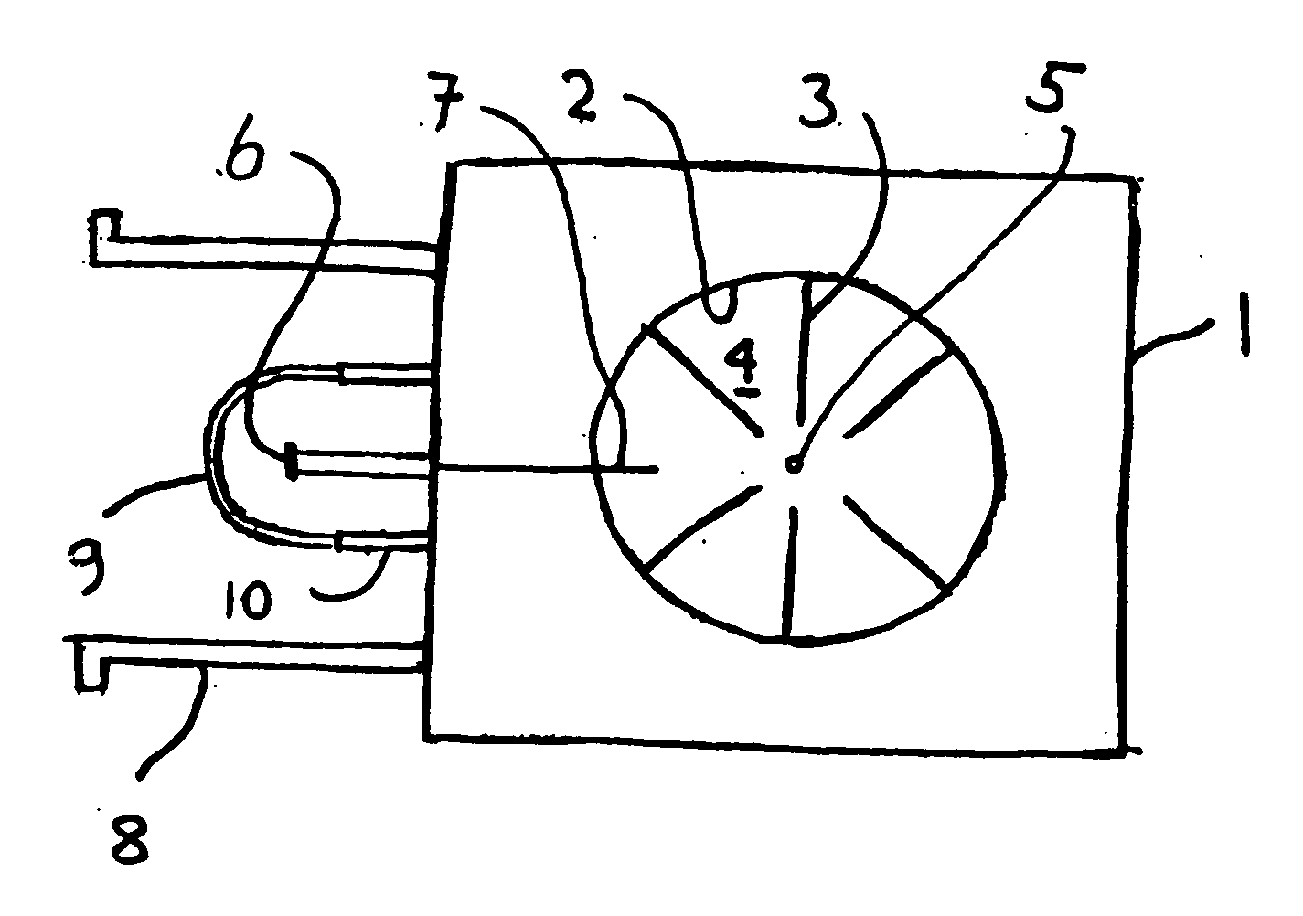
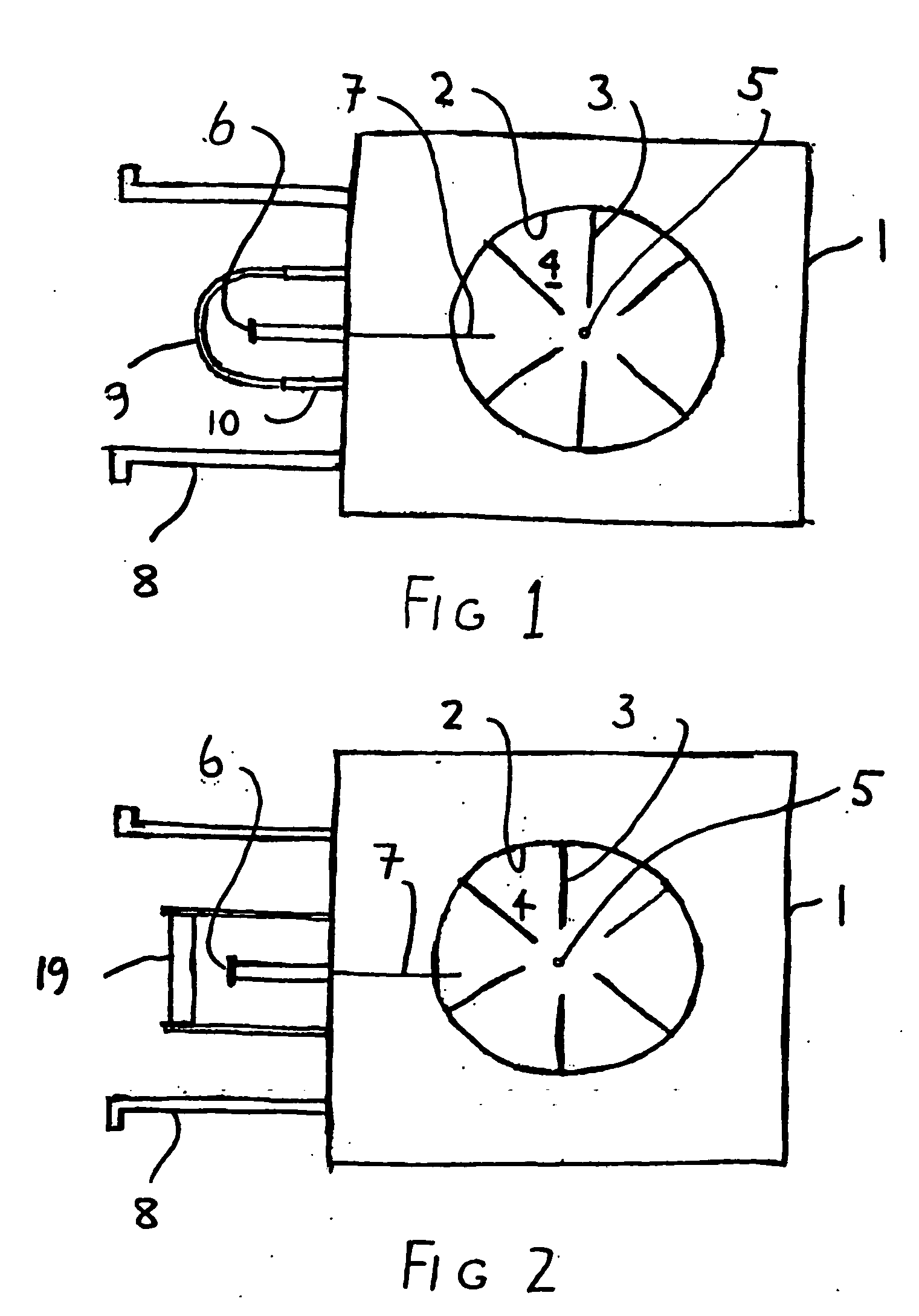
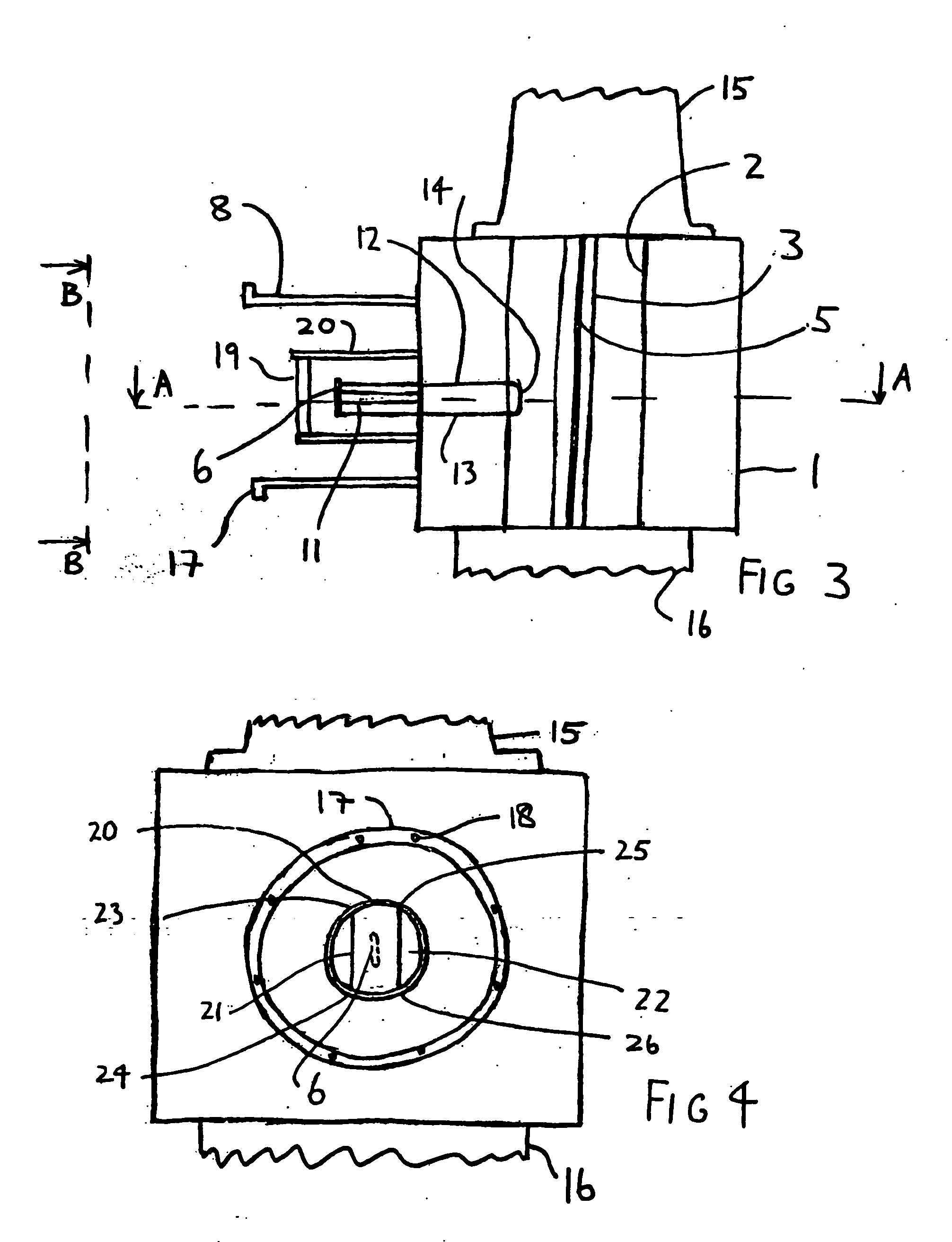
[0017] Referring to FIGS. 2 to 5, the magnetron according to the invention comprises a longitudinally-extending anode 2 in a main body 1 having inwardly-extending vanes 3 defining resonant cavities 4, and a central coaxial cathode 5. Electrons emitted from the negatively-charged cathode interact with a magnetic field parallel to the axis of the anode generated by e.g. electromagnets (not shown), to generate r.f. energy by resonant interaction with the cavities. An antenna 6 extending parallel the axis of the anode is supported by a post 11 of copper, one quarter wavelength long so as to have no electrical effect but just provide mechanical support and heat conduction. The antenna is connected by conductors 12, 13 to a loop 14 in a resonant cavity 4.

[0018] The cathode 5 extends above the main body in a region closed by cover 15. Beneath the main body 1, a portion 16 contains means for cooling the main body portion of the magnetron, which is typically made of copper.

[0019] The r.f. ...


PUM


Abstract

In a magnetron having a body 1 defining an anode 2 divided into resonant cavities 4 by vanes 3 and having a coaxial cathode 5, r.f. energy produced when a magnetic field is applied parallel to the axis of the anode is launched along a waveguide 8 by an antenna 6 in an evacuated region of the magnetron closed by a dielectric window 19. The latter has sector shaped conducting areas on its surface symmetrically arranged with respect to the antenna, the inductance of which balance the capacitance of the dielectric window, thereby reducing reflections at the window.

Description

CROSS-REFERENCE TO RELATED APPLICATION [0001] This application claims the priority of British Patent Application No. 0506580.0 filed on Mar. 31, 2005, the subject matter of which is incorporated herein by reference. BACKGROUND OF THE INVENTION [0002] This invention relates to magnetrons. [0003] Magnetrons typically include (FIG. 1) a main body portion 1, an anode 2, often with vanes 3 to define resonant cavities 4, a coaxial cathode 5, means (not shown) for setting up a magnetic field parallel to the axis of the cathode, and an antenna 6 coupled to a probe 7 in a resonant cavity 4, for launching r.f. energy into a waveguide 8. The space between the anode and the cathode is evacuated, and the antenna 6 is also within the evacuated region, a glass dome 9 connected to a copper sleeve 10 forming part of the envelope. [0004] The thickness of the glass dome 9 is not great, so the effect on the electrical length of the output is not great and, while the window does cause a mismatch because...

Claims


Application Information

Patent Timeline
Patent Type & Authority Applications(United States)
IPC IPC(8): H01J25/50H01J23/40H01J25/587
CPCH01J25/587H01J23/40
Inventor BRADY, MICHAEL BARRY CLIVE
Owner E2V TECH (UK) LTD
Why Eureka
Try Eureka