
Door assembly for a cooking appliance

a technology for cooking appliances and door assemblies, which is applied in the field of oven door assemblies, can solve the problems of increasing the overall thickness of the door, occupying a significant amount of insulation material,

Inactive Publication Date: 2006-10-05
MAYTAG
View PDF1 Cites 45 Cited by
  • Summary
  • Abstract
  • Description
  • Claims
  • Application Information

AI Technical Summary

Benefits of technology

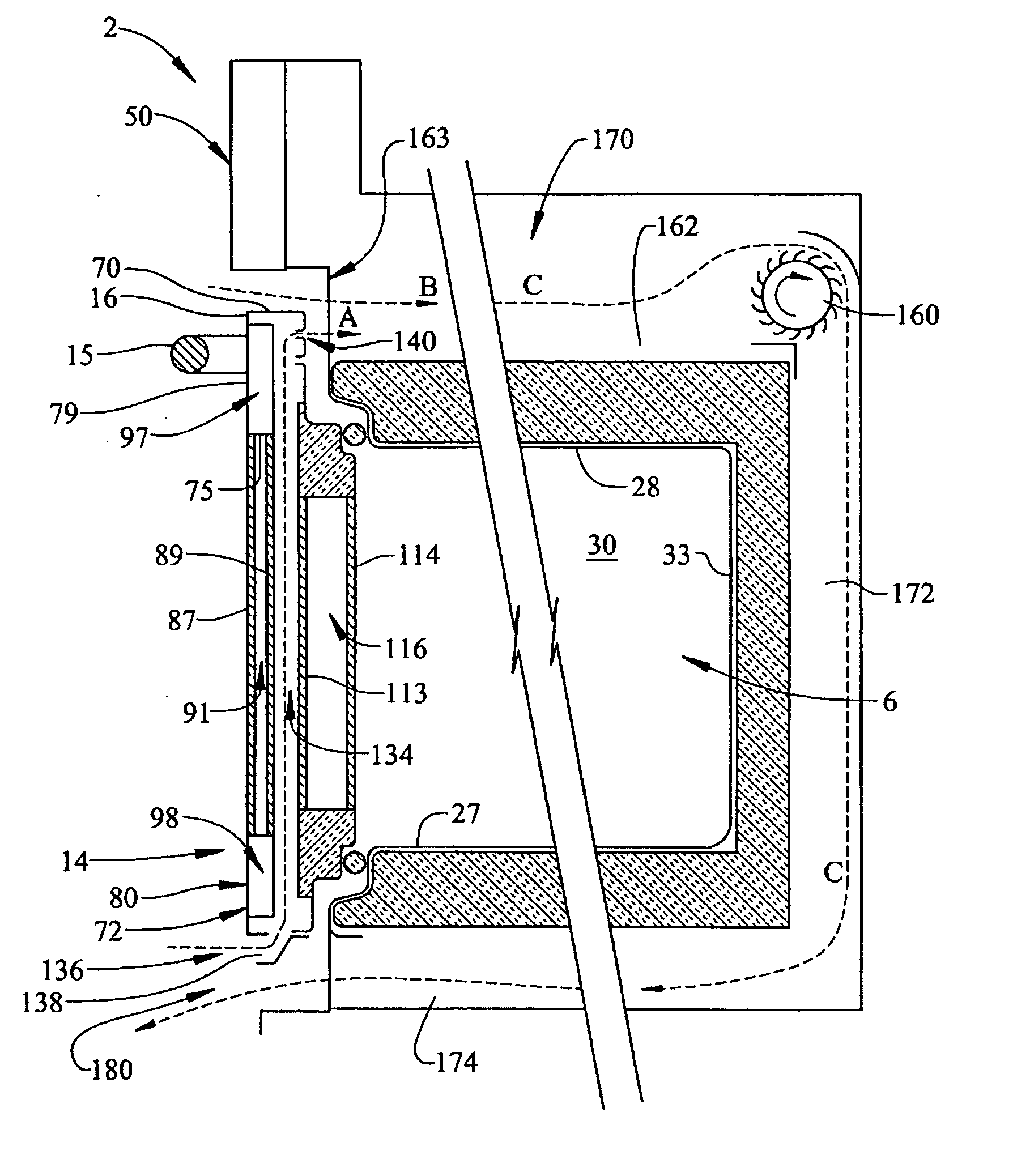
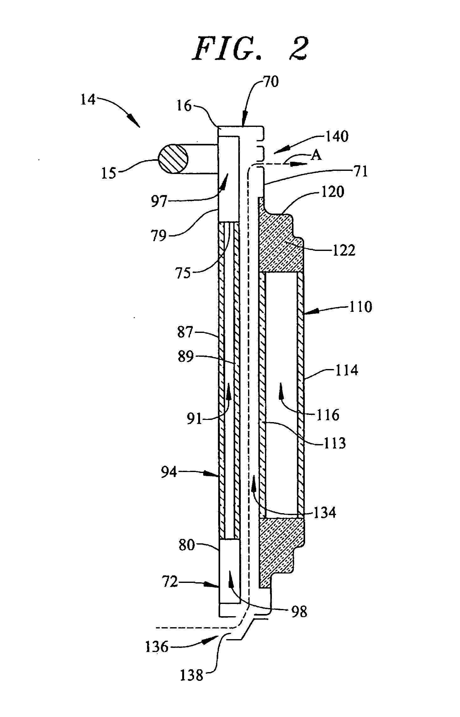
[0008] In addition to the inner window pack, the most preferred form of the invention actually provides the door with inner and outer transparent panes that form an outer window pack. More specifically, the inner and outer transparent panes of the outer window pack are spaced from and substantially parallel to one another so as to establish an outer dead air space. In addition to the insulation provided by the inner and outer window packs, further insulation is provided by upper and lower dead air spaces that are positioned above and below the outer window pack. With this construction, a uniform insulating layer that extends from a top portion to a bottom portion of the front panel is established. The uniform insulating layer, in combination with the inner dead air spaces, establishes an overall thermal barrier that minimizes heat transfer from the oven cavity to the front surface of the door. In accordance with the invention, the convective air flow through the passage contributes to an overall cooling air flow which is directed about the oven cavity and then exhausted.

Problems solved by technology

In an oven door that is not provided with a window or transparent zone for visually inspecting the contents of an oven cavity, a significant amount of room exists for insulation material.
In addition, incorporating window panes into an oven door will necessarily increase an overall thickness of the door as space must be provided for a thermal insulation barrier.

Method used


Image

  • Door assembly for a cooking appliance
  • Door assembly for a cooking appliance
  • Door assembly for a cooking appliance

Examples


Embodiment Construction

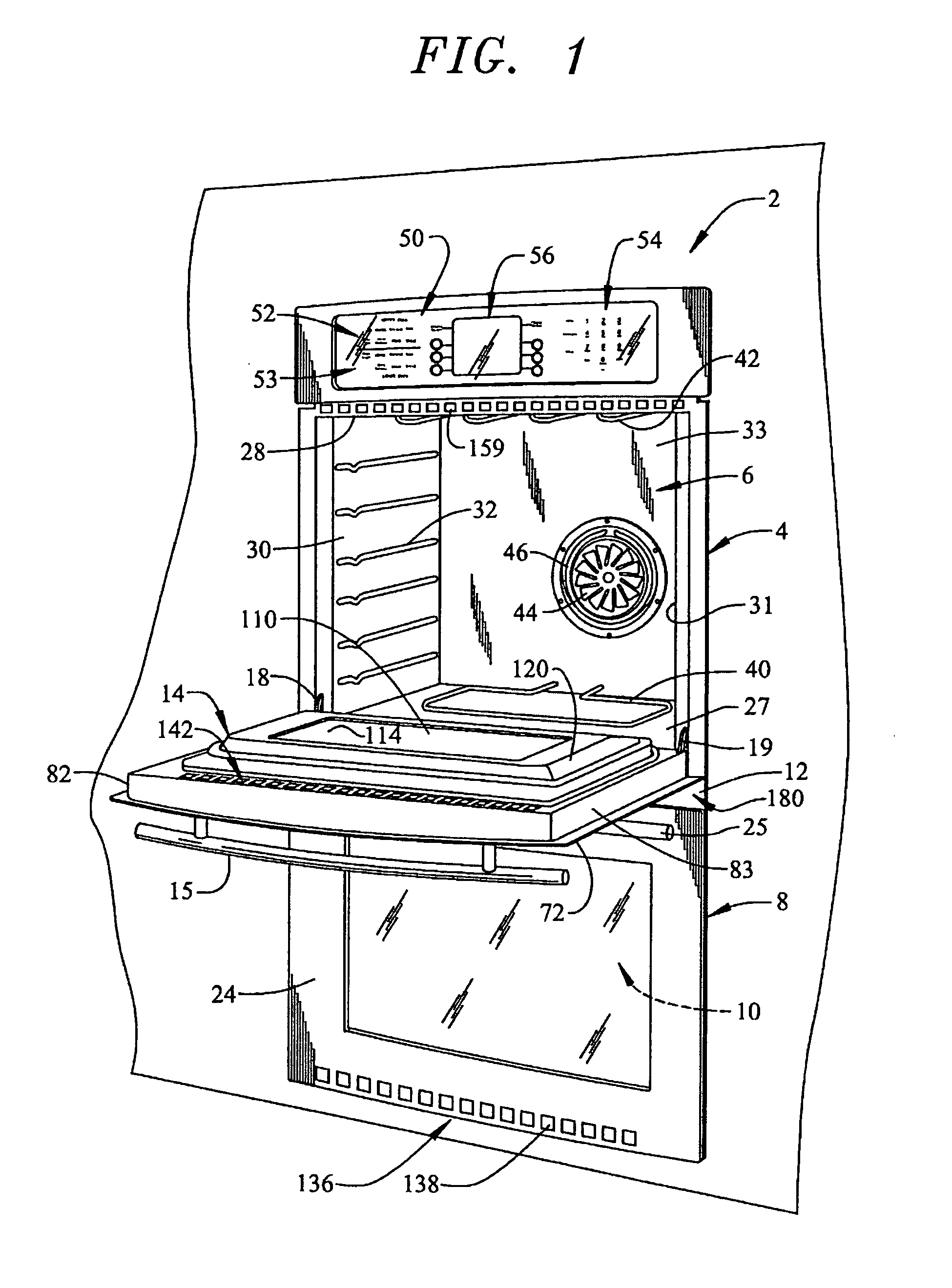
[0013] With initial reference to FIG. 1, a cooking appliance constructed in accordance with the present invention is generally indicated at 2. Cooking appliance 2, as depicted, constitutes a double wall oven. However, it should be understood that the present invention is not limited to this model type and can be incorporated into various types of oven configurations, e.g., cabinet mounted ovens, as well as both slide-in and free standing ranges. In any event, in the embodiment shown, cooking appliance 2 constitutes a dual oven wall unit including an upper oven 4 having upper oven cavity 6 and a lower oven 8 having a lower oven cavity 10. Cooking appliance 2 includes an outer frame 12 for supporting both upper and lower oven cavities 6 and 10 within, for example, a wall (not separately labeled).

[0014] Cooking appliance 2 includes a door assembly 14 to selectively provide access to upper oven cavity 6. As shown, door assembly 14 includes a handle 15 that enables a consumer to grasp a...


PUM


Abstract

A cooking appliance includes an oven door having a transparent zone and a passage for permitting an air flow to pass through the door and into a cooling duct extending about an oven cavity. The door includes a panel having a front surface and a central opening in which is arranged an outer transparent pane. The passage separates the outer transparent pane from an inner window pack. The inner window pack includes first and second, substantially parallel window panes spaced one from the other to establish an inner dead air space. Preferably, the door includes an inner transparent pane that forms, with an outer transparent pane, an outer window pack which establishes an outer dead air space. The outer dead air space is positioned between upper and lower portions of the oven door that establish additional dead air spaces that form an overall uniform insulating layer for the door.

Description

BACKGROUND OF THE INVENTION [0001] 1. Field of the Invention [0002] The present invention pertains to the art of cooking appliances and, more particularly, to an oven door assembly having inner and outer insulating dead air spaces and a convection air passage. [0003] 2. Discussion of the Prior Art [0004] Ovens and their general construction are well known. Typically, an oven includes a cooking cavity having an opening which is selectively closed by a pivotally mounted door assembly. Usually, ovens are of two general configurations, built-in units, i.e. built into cabinet or wall structure, or slide-in and free standing units generally combined with cooktops which are commonly referred to as oven ranges. The doors furnished with ovens can be composed of multiple components which can include a sealing panel, thermal insulation, a window, an intermediate panel, an outer panel, handles, hinges and, in some instances, a decorative face covering made of metal, glass or the like. [0005] On...

Claims


Application Information

Patent Timeline
Patent Type & Authority Applications(United States)
IPC IPC(8): F24C15/02
CPCF24C15/04F24C15/006
Inventor LARSEN, CHRISTOPHER A.
Owner MAYTAG
Learn More