Gas flow control assembly for use with fuel cell systems operating on fuels with varying fuel composition

a technology of gas flow control and fuel cell system, which is applied in the field of fuel cells, can solve the problems of significant decline in reliability of online fuel composition analyzer, expensive and complex equipment used in conventional methods of controlling the flow rate of fuel to the anodes, and the need for expensive and complex equipmen

Active Publication Date: 2006-09-28
FUELCELL ENERGY INC
View PDF10 Cites 7 Cited by
  • Summary
  • Abstract
  • Description
  • Claims
  • Application Information

AI Technical Summary

Benefits of technology

[0008] In accordance with the principles of the present invention, the above and other objectives are realized in a gas flow control assembly for use in a fuel cell system comprising an airflow control assembly for adjusting flow of air to a cathode side of the fuel cell system based on or responsive to content variations in an exhaust gas leaving an anode side of the system and a fuel flow control assembly for controlling flow of fuel to the anode side of the fuel cell system based on adjustment to the airflow by the airflow control assembly. The fuel cell system includes an oxidizing assembly adapted to preheat air using the anode exhaust gas comprising unreacted fuel and the airflow control assembly adjusts the airflow so as to preheat the air in the oxidizing assembly to a predetermined temperature. The airflow control assembly includes an air trim controller for adjusting the airflow set point and an airflow controller for maintaining an air flow rate equal to the adjusted airflow set point to the system, the air trim controller comparing the temperature of the preheated air with the predetermined temperature to determine an adjustment value and adjusting the airflow set point based on the adjustment value. The air flow set point is a predetermined air flow rate based on the DC current, desired fuel flow, expected fuel heating value and ambient temperature. The air trim controller lowers the adjustment value if the temperature of the preheated air is less than the predetermined temperature and raises the adjustment value if the temperature of the preheated air is greater than the predetermined temperature, and the adjustment value is directly proportional to the airflow adjustment.
[0009] The fuel flow control assembly includes a fuel trim controller for adjusting the fuel flow set point to the system and a fuel flow controller to measure and maintain the fuel flow rate at adjusted fuel flow set point. The fuel flow set point is a predetermined fuel flow rate based on the DC current, desired excess over the minimum required fuel flow, and the expected fuel heating value. The fuel trim controller receives the adjustment value calculated by the air trim controller and modulates the fuel flow set point so as to maintain the air trim controller adjustment value in a predetermined range. In particular, the air trim controller raises and lowers the adjustment value incrementally by a set amount, e.g., 1, for increases and decreases, respectively, in the temperature of preheated air when the temperature is greater than the predetermined temperature, and lowers and raises the adjustment value incrementally by the set amount, e.g., 1, for decreases and increases, respectively, in the temperature of preheated air when the temperature is smaller than the predetermined temperature, and the fuel trim controller adjusts the fuel flow set point so as to maintain the air trim controller adjustment value between 0 and minus (−) the set amount, e.g., 1.
[0010] Also disclosed is a fuel cell system employing the gas flow control assembly.

Problems solved by technology

As can be appreciated, these conventional methods of controlling the flow rate of the fuel to the anodes require use of expensive and complex equipment.
In addition, the reliability of the online fuel composition analyzer significantly declines when the fuel being analyzed has a high moisture content and also after prolonged operation of the analyzer.

Method used


Image

  • Gas flow control assembly for use with fuel cell systems operating on fuels with varying fuel composition
  • Gas flow control assembly for use with fuel cell systems operating on fuels with varying fuel composition
  • Gas flow control assembly for use with fuel cell systems operating on fuels with varying fuel composition

Examples


Embodiment Construction

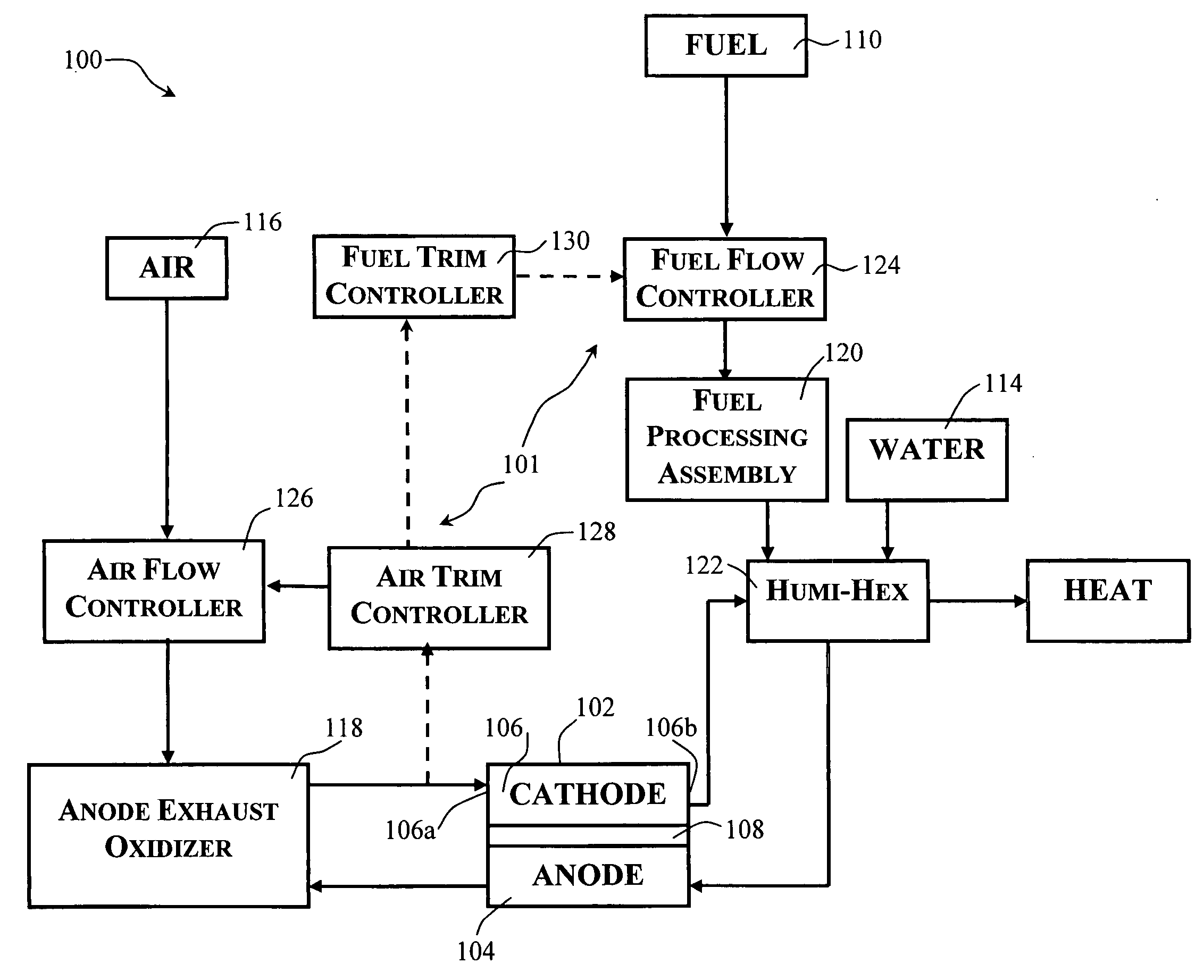
[0016]FIG. 1 shows a fuel cell system 100 employing a gas flow control assembly 101 in accord with the principles of the present invention. The gas flow control assembly 101 includes a fuel flow controller 124 which may include a fuel flow meter and an automated control valve, an airflow controller 126 which may include an air flow meter and an automated control valve, an air trim controller 128 and a fuel trim controller 130, all used to control the flow of fuel and air to the anode side 104 and the cathode side 106, respectively, of a fuel cell 102 of the system 100. The anode and cathode sides of the fuel cell 102, are, in turn, separated by an electrolyte 108.

[0017] The fuel cell system also includes a fuel supply 110 for supplying fuel gas to the anode side 104 of the fuel cell 102, a water supply 114 for humidifying the fuel gas, an air supply 116 for supplying oxidant gas to the cathode side 106 of the fuel cell 102 and an anode exhaust oxidizer 118. A fuel processing assemb...


PUM

PropertyMeasurementUnit
temperatureaaaaaaaaaa
volumeaaaaaaaaaa
DC currentaaaaaaaaaa

Abstract

A gas flow control assembly for use in a fuel cell system comprising an airflow control assembly for adjusting flow of air to a cathode side of the fuel cell system based on content variations in an exhaust gas leaving an anode side of the system and a fuel flow control assembly for controlling flow of fuel to the anode side based on adjustment to the airflow by the airflow control assembly.

Description

BACKGROUND OF THE INVENTION [0001] This invention relates to fuel cells and, in particular, to a gas flow control assembly for use in fuel cell systems. [0002] A fuel cell is a device, which directly converts chemical energy stored in hydrocarbon fuel into electrical energy by means of an electrochemical reaction. Generally, a fuel cell comprises an anode and a cathode separated by an electrolyte, which serves to conduct electrically charged ions. In order to produce a useful power level, a number of individual fuel cells are stacked in series with an electrically conductive separator plate between each cell. [0003] Fuel cells operate by passing a reactant fuel gas through the anode, while oxidizing gas is passed through the cathode. The electrical output of the fuel cell system depends in part on the rates at which the fuel gas and the oxidizing gas are supplied to, and are carried through, the anode and the cathode, respectively, as well as on the energy content of the fuel. There...

Claims


Application Information

Patent Timeline
Patent Type & Authority Applications(United States)
IPC IPC(8): H01M8/04
CPCH01M8/04022H01M8/04089H01M8/04335Y02E60/50H01M8/04462H01M8/04753H01M8/04388H01M8/04
Inventor VENKATARAMAN, RAMAKIRSHNANBERNTSEN, GEORGECARLSON, GLENN L.JAHNKE, FRED C.LEO, ANTHONY J.
Owner FUELCELL ENERGY INC
Why Eureka
Try Eureka