
Reduction of driving voltage in a switchable element

Active Publication Date: 2006-09-28
KONINKLIJKE PHILIPS ELECTRONICS NV
View PDF6 Cites 15 Cited by
  • Summary
  • Abstract
  • Description
  • Claims
  • Application Information

AI Technical Summary

Benefits of technology

[0009] It is an object of the present invention to eliminate, or at least alleviate, the above described problems related to power consumption and actuation voltage in electro-wetting devices.
[0011] The invention is based on a realization of the inventors, that by affecting the surface tension of the liquids in an optical element, one can lower the voltage needed to control the optical cell without substantially altering its optical performance.
[0017] A switchable device, wherein the surface tension between the cell wall and said first or second liquids, as defined in claim 3 or 4, has the advantage of enabling an adjustment of the contact angle in the OFF-state, which does not influence the sensitivity of the contact angle with respect to the applied voltage.

Problems solved by technology

If the actuation voltage is too high it might be necessary to include additional electronics to drive the device.
Such additional electronics has a number of drawbacks, one being increased development and manufacturing costs of the device.
Another drawback related to a high power consumption might be that batteries of the portable device need to be recharged so frequently, that use of the portable device is substantially restricted.

Method used


Image

  • Reduction of driving voltage in a switchable element
  • Reduction of driving voltage in a switchable element
  • Reduction of driving voltage in a switchable element

Examples


Embodiment Construction

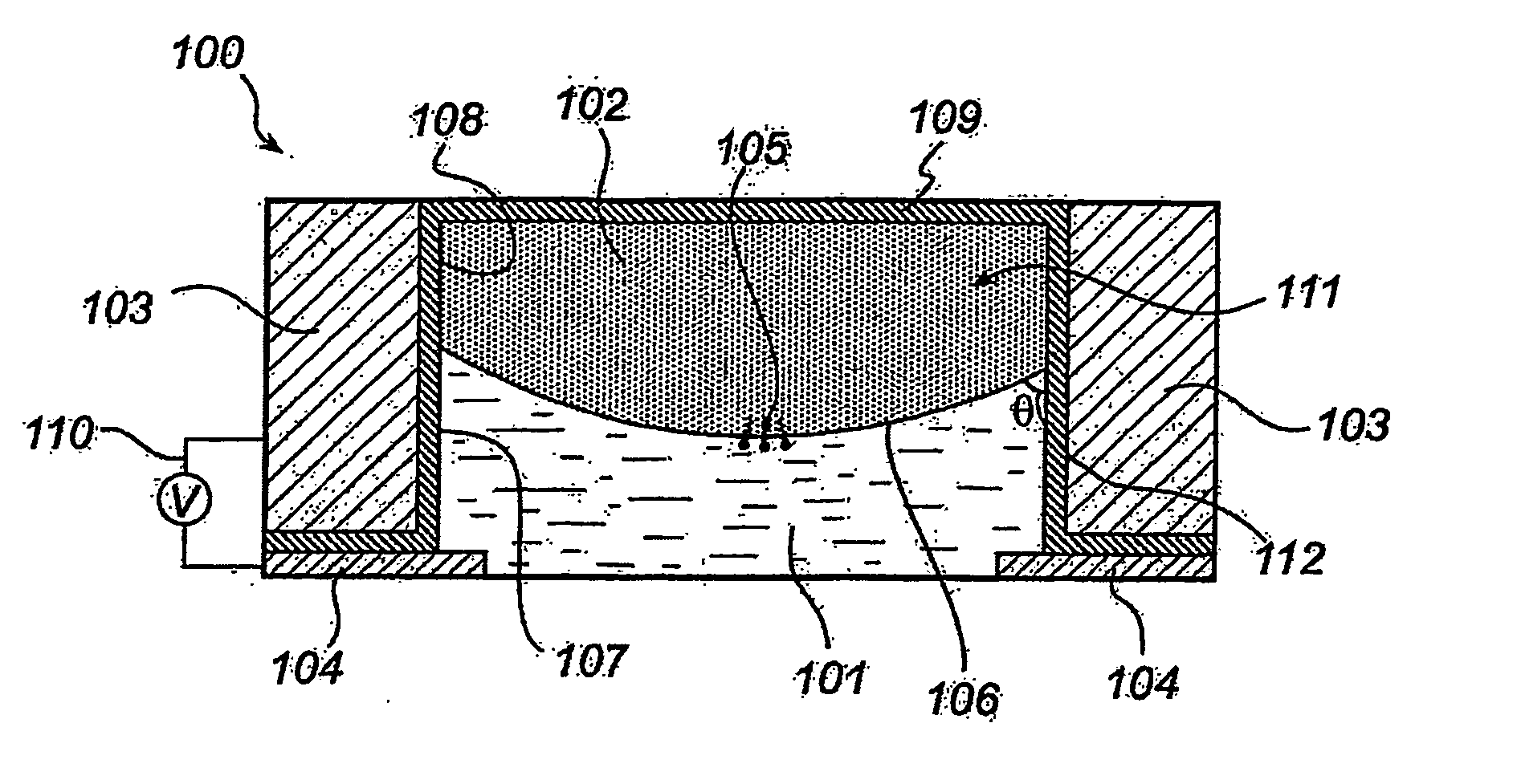
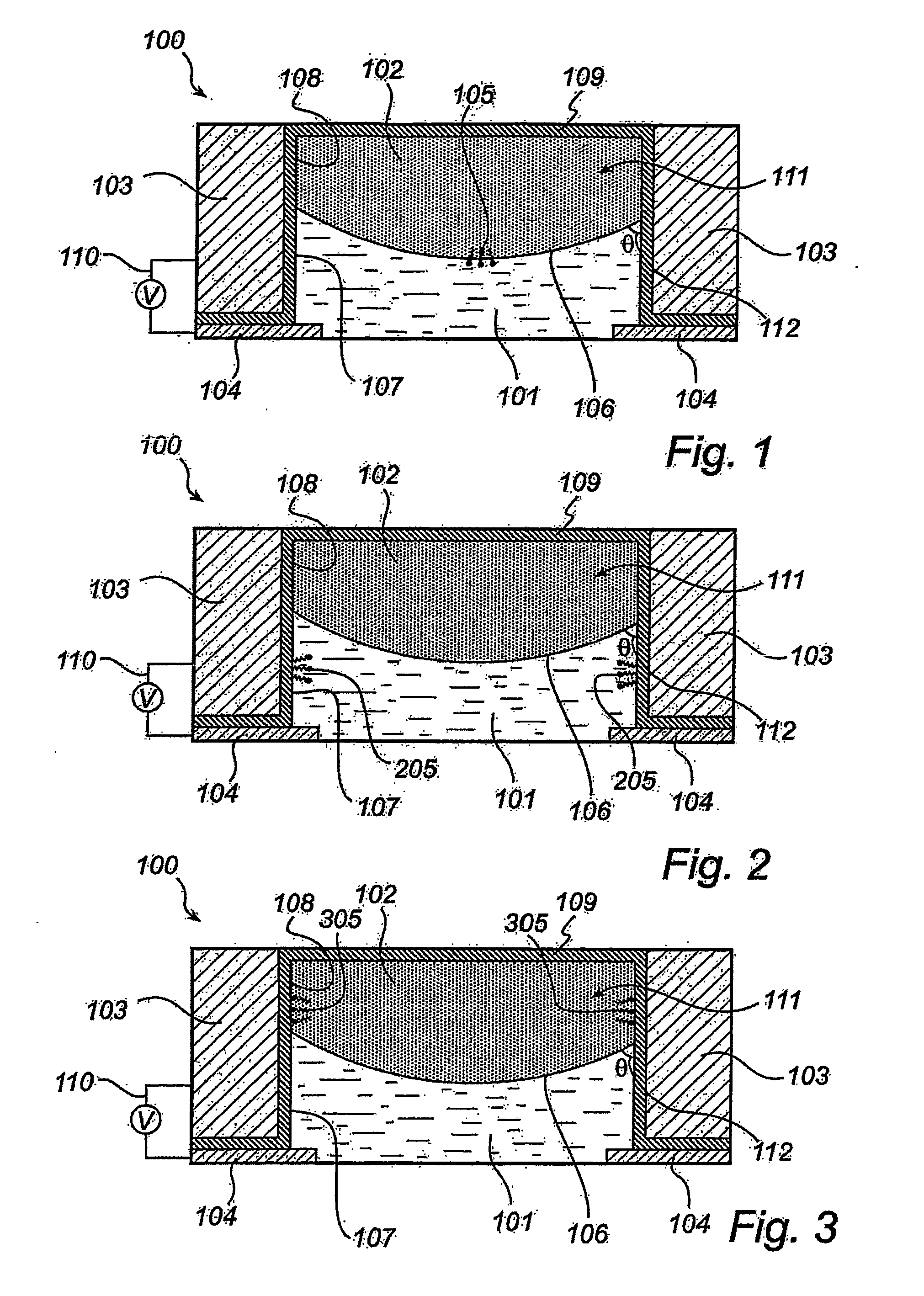
[0023] In this description, identical or corresponding parts have identical or corresponding reference numerals. The invention will now be described in further detail, with reference to FIG. 1. Although FIG. 1 illustrates a switchable element, which is used as an variable focus lens, it is understood that the invention applies equally well to other kinds of electro-wetting elements, such as motors, variable diaphragms, filters, gratings, beam deflectors, motors and electro-wetting based displays.

[0024]FIG. 1 schematically shows a side view of a switchable optical element 100. The switchable optical element 100 comprises a closed cell or fluid chamber 111, which contains a first 101 and a second 102 body of fluid. Said fluids 101, 102 are substantially immiscible. Said first fluid 101 preferably is water, which is a polar and electrically conducting fluid, or liquid, and said second fluid 102 preferably is oil, which is a non-polar liquid. When a polar and a non-polar liquid are in ...


PUM


Abstract

A switchable element is described, which comprises a fluid chamber (111) containing a polar (101) and a non-polar (102) liquid, which are immiscible. The element is further provided with two electrodes (103,104), which are arranged to control the spatial distribution of the liquids, by means of an applied voltage across two the two electrodes. By the addition of surfactant to one or both of the liquids, the actuation voltage of the element is lowered. The element can work for example as an optical device or a motor.

Description

FIELD OF THE INVENTION [0001] The present invention relates to switchable elements, and to devices including switchable elements. TECHNICAL BACKGROUND [0002] Electro-wetting is essentially the phenomenon whereby an electric field modifies the wetting behavior of a polar liquid in contact with a hydrophobic surface. By applying an electric field, a surface energy gradient is created in the polar liquid, which can be used to manipulate the liquid. In common applications, water is used as the polar liquid. [0003] Recently, switchable elements have been proposed and demonstrated to operate based on the principle of electro-wetting. Such switchable elements typically consist of a closed cell that is filled with one part of water and one part of oil, although other liquids might also be used. The important characteristics are that the liquids are immiscible and that one of them is polar and or electrically conducting (e.g. water), while the other one is non-polar (e.g. oil). Other liquid ...

Claims


Application Information

Patent Timeline
IPC IPC(8): G02B3/12G02B3/14G02B26/02
CPCG02B3/14G02B26/005G02B3/12
Inventor KUIPER, STEINRENDERS, CHRISTINA ADRIANAHENDRIKS, BERNARDUS H.W.HAYES, ROBERT ANDREW
Owner KONINKLIJKE PHILIPS ELECTRONICS NV
Learn More