
Timing recovery circuit with multiple stages

Active Publication Date: 2006-09-28
SOCIONEXT INC
View PDF13 Cites 6 Cited by
  • Summary
  • Abstract
  • Description
  • Claims
  • Application Information

AI Technical Summary

Benefits of technology

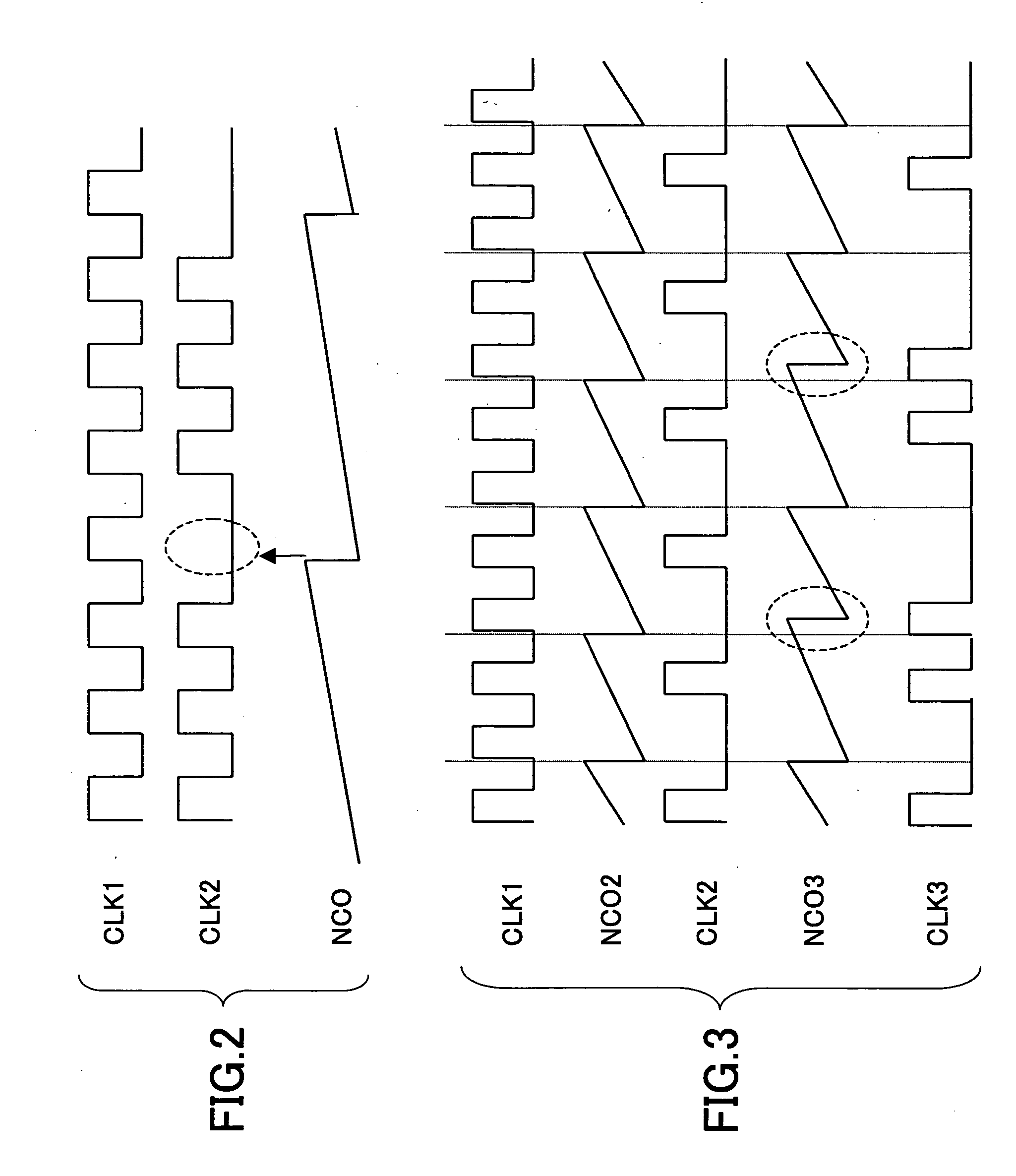
[0026] According to at least one embodiment of the present invention, the symbol timing recovery circuit divides the decimation of a clock signal into a plurality of decimation stages, so that there are a portion that performs a decimation process utilizing a fixed decimation rate without being affected by jitter, and another portion that performs a decimation process using a feedback-based decimation rate with the effect of jitter being present. These portions are combined together to achieve a desired decimation rate. In this configuration, the decimation process utilizing the fixed decimation rate allows the decimation rate of the feedback-based decimation process to be lowered. Accordingly, the effect of jitter on the feedback-based decimation process can be reduced.

Problems solved by technology

However, the distribution of clock pulses is extremely uneven.
This cannot achieve such proper decimation that the values of data identifying points and the values of zero-crossing points are properly left.
As a result, the recovery of the received signal becomes inaccurate, causing degradation in the signal reception performance.
Further, degradation in the performance increases at the points where the decimation rate is a reciprocal of an integer number such as the points corresponding to an NCO revolution ratio of 3 and 4 (decimation rate of 1 / 3 and 1 / 4).
Such a configuration using a plurality of clocks, however, gives rise to a problem that the circuit becomes complex and the circuit size increases.
Further, it is difficult to switch clocks seamlessly, thereby giving rise to a problem that the symbol rate cannot be easily changed.

Method used


Image

  • Timing recovery circuit with multiple stages
  • Timing recovery circuit with multiple stages
  • Timing recovery circuit with multiple stages

Examples


first embodiment

[0048]FIG. 7 is a drawing showing the configuration of the symbol timing recovery circuit according to the present invention. The symbol timing recovery circuit of FIG. 7 includes a clock control circuit 31, a flip-flop 32, a digital filter 33, a phase comparator 34, a loop filter 35, an NCO 36, a tap coefficient computing unit 37, a clock control circuit 41, a flip-flop 42, a digital filter 43, a tap coefficient computing unit 44, and an NCO 45.

[0049] The clock control circuit 31, the flip-flop 32, the digital filter 33, and the tap coefficient computing unit 37 correspond to the second decimation circuit 21 of FIG. 5. The phase comparator 34 and the loop filter 35 correspond to the phase-comparison & loop-filter 24 of FIG. 5. The NCO 36 corresponds to the second NCO 23 of FIG. 5. The clock control circuit 41, the flip-flop 42, the digital filter 43, and the tap coefficient computing unit 44 correspond to the first decimation circuit 20 of FIG. 5. The NCO 45 corresponds to the firs...

second embodiment

[0065]FIG. 9 is a drawing showing the configuration of the symbol timing recovery circuit according to the present invention. In FIG. 9, the same elements as those of FIG. 7 are referred to by the same numerals, and a description thereof will be omitted.

[0066] In the symbol timing recovery circuit shown in FIG. 9, the role of the first-stage decimation process and the role of the second-stage decimation process are reversed, compared with the symbol timing recovery circuit shown in FIG. 7. In the configuration shown in FIG. 7, the decimation process with a fixed decimation rate is performed at the first stage, and the decimation process with a feedback-control-based decimation rate is performed at the second stage. In the configuration shown in FIG. 9, on the other hand, the decimation process with a feedback-control-based decimation rate is performed at the first stage, and the decimation process with a fixed decimation rate is performed at the second stage. Namely, the output of t...


PUM


Abstract

A timing recovery circuit includes a first oscillating circuit configured to produce a first timing signal, a second oscillating circuit configured to produce a second timing signal, a first decimation circuit coupled to a supply node of a first clock signal and to the first oscillating circuit to produce a second clock signal made by decimating pulses of the first clock signal in response to the first timing signal, and a second decimation circuit coupled to the first decimation circuit and to the second oscillating circuit to produce a third clock signal made by decimating pulses of the second clock signal in response to the second timing signal, wherein one of the first timing signal and the second timing signal has a fixed cycle, and another one has a cycle responsive to feedback control.

Description

CROSS-REFERENCE TO RELATED APPLICATIONS [0001] The present application is based upon and claims the benefit of priority from the prior Japanese Patent Application No. 2005-093004 filed on Mar. 28, 2005, with the Japanese Patent Office, the entire contents of which are incorporated herein by reference. BACKGROUND OF THE INVENTION [0002] 1. Field of the Invention [0003] The present invention generally relates to receiver circuits that synchronize the receiver side with the transmitter side, and particularly relates to a symbol timing recovery circuit that recovers the symbol timing on the receiver side. [0004] 2. Description of the Related Art [0005] In high-speed serial communications, provision is made to avoid the transmission of a clock signal as a separate signal from communication data, thereby reducing the number of communication lines. On the data receiving side, the communication data transmitted from the transmitter side need to be properly received. To this end, a symbol ti...

Claims


Application Information

Patent Timeline
IPC IPC(8): H03M7/34
CPCH04L7/0012H04L7/0029H04L7/0331
Inventor KANAZASHI, KAZUYUKI
Owner SOCIONEXT INC
Learn More