
Power generation controller

Active Publication Date: 2006-09-28
DENSO CORP
View PDF12 Cites 6 Cited by
  • Summary
  • Abstract
  • Description
  • Claims
  • Application Information

AI Technical Summary

Benefits of technology

[0015] With the power generation controller of this invention configured to control the excitation current of a generator driven by an internal combustion engine on the basis of a control command transmitted from an external control unit located in the vicinity of the engine for controlling the engine when the engine is in a stopped state, it becomes possible to prevent noise emitted from the engine from mixing with the control command, to thereby improve the reliability of a vehicle generator control system.

Problems solved by technology

Accordingly, there has been a possibility that noise which the vehicle engine emits from its ignition device is incorporated into the binary pulse train signal transmitted from the engine ECU to the power generation voltage controller.
However, since the power generation voltage controller cannot continue to perform the control operation on the basis of the binary pulse train signal including error, it is necessary for the power generation voltage controller to perform the control operation on the basis of the previously received binary pulse train signal, or to change to internal control mode when the power generation voltage controller detects error in the received binary pulse train signal.
This prevents the power generation voltage controller from performing optimum control.
Furthermore, in a case where error in the binary pulse train signal due to the noise cannot be detected, there is a problem in that the power generation voltage controller erroneoulsy controls the vehicle generator at least until it next receives the binary pulse train signal.

Method used


Image

  • Power generation controller
  • Power generation controller
  • Power generation controller

Examples


Embodiment Construction

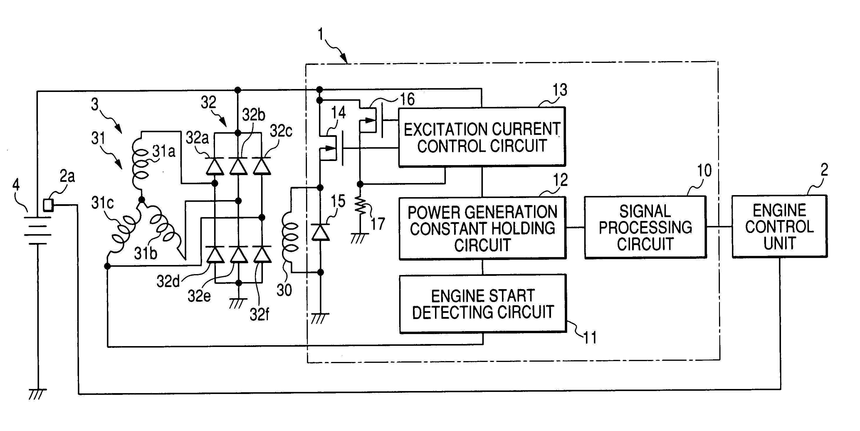
[0025]FIG. 1 is a block diagram showing a structure of a power generation controller 1 according to a first embodiment of the invention, which is used for controlling a vehicle generator driven by a vehicle internal combustion engine.

[0026] As shown in FIG. 1, the power generation controller 1 is connected to an engine control unit 2, vehicle generator 3, and a vehicle battery 4.

[0027] The engine control unit 2 operates to control the vehicle engine on the basis of characteristic values (velocity, acceleration, etc.) received from various sensors mounted on the vehicle. The engine control unit 2 also operates to generate a control command and transmits it to the power generation controller 1 in the form of a pulse train signal through a signal cable 2b. The engine control unit 2 is connected to a temperature sensor 2a detecting the temperature of the vehicle battery 4.

[0028] The control command includes a gradual-excitation time command, a maximum power increase command, a gradua...


PUM


Abstract

The power generation controller includes a control command receiving section receiving a control command transmitted from an external control unit for controlling an internal combustion engine, a control command holding section holding the control command received by the control command receiving section, and an excitation current control section controlling an excitation current of a generator driven by the internal combustion engine on the basis of the control command held by the control command holding section. The excitation current control section is configured to control the excitation current on the basis of a control command transmitted from the external control unit when the internal combustion engine is in a stopped sate.

Description

CROSS-REFERENCE TO RELATED APPLICATION [0001] This application is related to Japanese Patent Application No. 2005-84846 filed on Mar. 23, 2005, the contents of which are hereby incorporated by reference. BACKGROUND OF THE INVENTION [0002] 1. Field of the Invention [0003] The present invention relates to a power generation controller for controlling a generator in accordance with a control command transmitted from an external control unit. [0004] 2. Description of Related Art [0005] It is known to regulate an output voltage of a vehicle generator driven by an engine mounted on a vehicle by use of a power generation voltage controller as disclosed in Japanese Patent Application Laid-open No. 8-275407. Such a power generation voltage controller includes a signal discriminating means connected to an engine ECU (Electronic Control Unit), a power generation voltage setting means, a voltage controlling comparator, and an excitation current controlling transistor connected to an excitation ...

Claims


Application Information

Patent Timeline
IPC IPC(8): H02H7/06H02P9/00H02P11/00
CPCH02P9/006H02P9/08H02P9/107Y02T10/92H02J7/1446H02P9/10H02P9/30H02P9/48
Inventor OKAHARA, HIDETOASADA, TADATOSHI
Owner DENSO CORP
Learn More