
Vehicle AC generator having connection portions of stator winding conductor segments oriented in accordance with direction of cooling air flow

a technology of connecting portions and conductor segments, which is applied in the direction of windings, dynamo-electric components, cooling/ventilation arrangements, etc., can solve the problems of increasing the level of audible noise, connecting portions (i, portions) of the conductor segments obstructing the flow of cooling air from the adjacent cooling fan, etc., and achieves the effect of reducing the noise caused by the cooling air passing over the connection portions

Inactive Publication Date: 2006-09-28
DENSO CORP
View PDF4 Cites 12 Cited by
  • Summary
  • Abstract
  • Description
  • Claims
  • Application Information

AI Technical Summary

Benefits of technology

[0010] It is an objective of the present invention to overcome the above disadvantages of the prior art by providing an AC generator for installation in a motor vehicle (referred to in the following simply as a vehicle AC generator) having a stator winding formed of sets of basically U-shaped conductor segments as described above, but whereby the degree of obstruction of a flow of cooling air due to the presence of the connection portions of the stator winding conductor segments can be substantially reduced, and the level of noise due the cooling air passing over the connection portions can also be reduced.
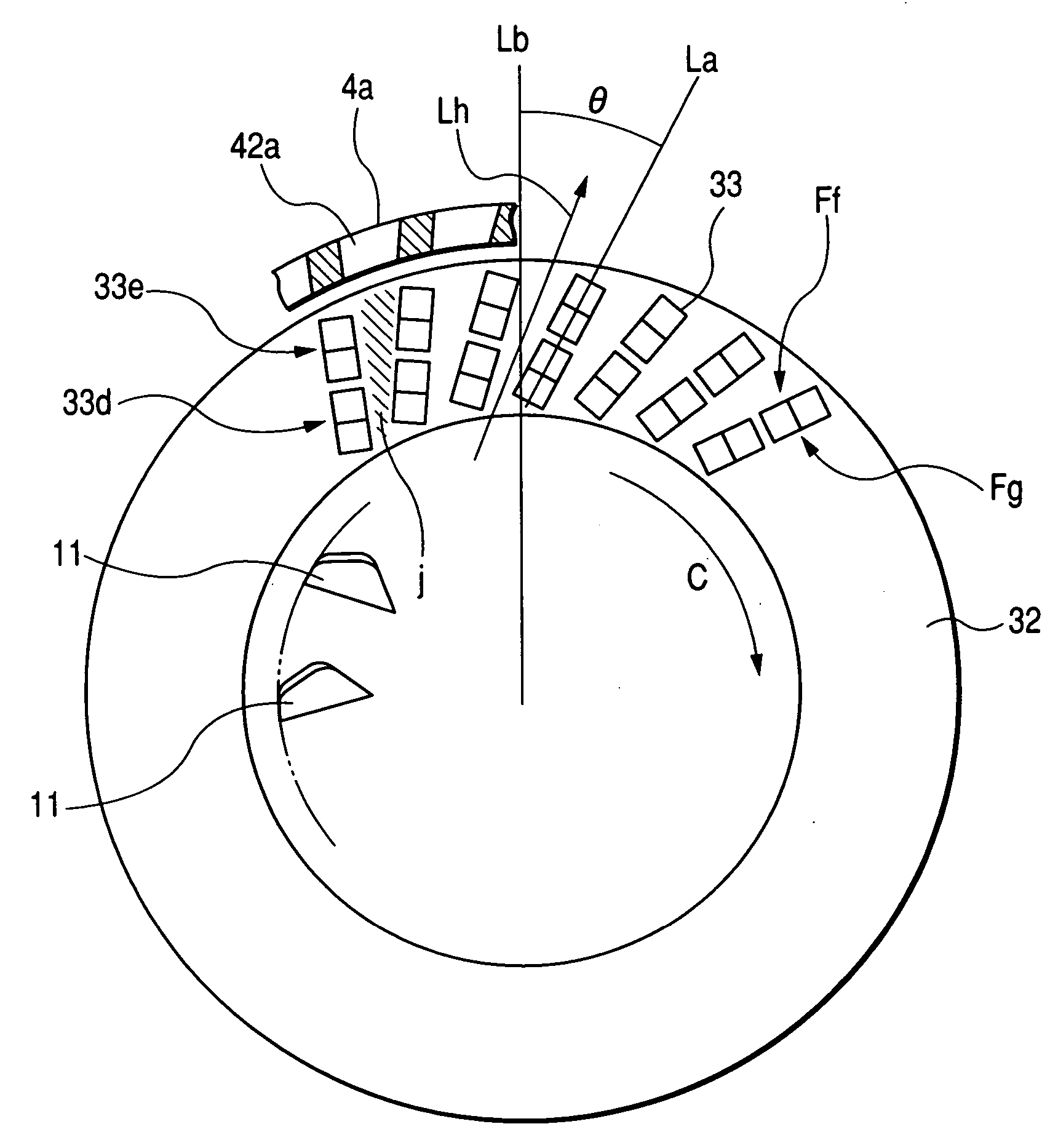
[0012] In that way, when a flow of cooling air is generated by utilizing rotation of the rotor and passes through the pairs of connected tip portions of the conductor segments, with the air flow being along a direction which is angularly displaced from a radially outward direction, it can be ensured that the amount of resistance presented to the cooling air flow by the tip portions of the conductor segments is reduced, while in addition the level of audible noise resulting from the flow of cooling air over the tip portions of the conductor segments.
[0015] From another aspect, when such a type of fan is utilized then in each pair of connected tip portions of conductor segments, the radially outer tip portion of the pair is preferably positioned ahead of the radially inner tip portion of the pair, with respect to the direction of rotation of the rotor. The resistance to the flow of cooling air can thereby be further decreased.

Problems solved by technology

However when the stator winding is formed as described above from such successively connected U-shaped conductor segments, with the connection portions are disposed adjacent to the outer circumference of one of the fans, the connection portions (i.e., pairs of connected tip portions) of the conductor segments obstruct the flow of cooling air from the adjacent cooling fan.
This is a significant problem, since achieving effective cooling of the interior of the rotary electric machine is an important factor in attaining increased operating capacity.
Moreover, as a result of the flow of cooling air over the connection portions of the stator winding, an increased level of audible noise is generated, by comparison with a conventional type of stator winding which does not incorporate such connection portions.

Method used


Image

  • Vehicle AC generator having connection portions of stator winding conductor segments oriented in accordance with direction of cooling air flow
  • Vehicle AC generator having connection portions of stator winding conductor segments oriented in accordance with direction of cooling air flow
  • Vehicle AC generator having connection portions of stator winding conductor segments oriented in accordance with direction of cooling air flow

Examples


Embodiment Construction

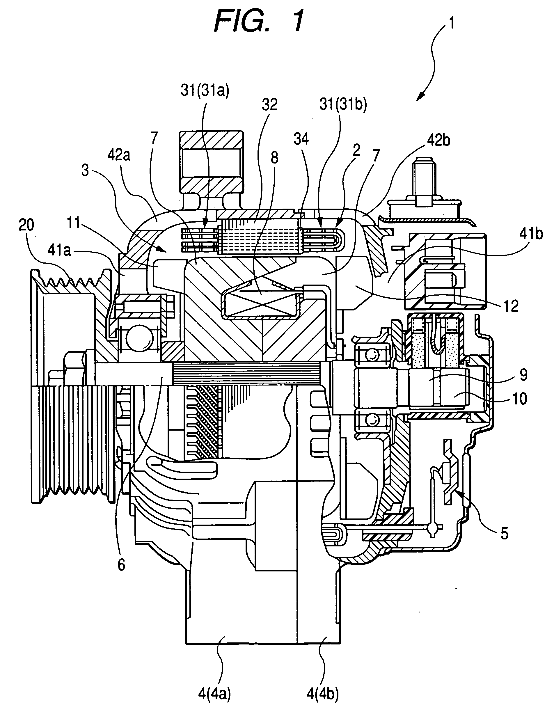
[0023] An embodiment of a vehicle AC generator will be described referring first to the overall configuration shown in the cross-sectional view of FIG. 1. The vehicle AC generator 1 of FIG. 1 is basically made up of a stator 2, a rotor 3, a frame 4, a rectifier apparatus 5 and a rotor shaft 6. The rotor 3 produces field magnet poles, and is fixedly attached to the rotor shaft 6, to be rotated thereby. The rotor 3 is made up of a Lundel type of pole core 7 (i.e., having a toothed circumferential configuration), a field coil 8, slip rings 9, 10, and a radial cooling fan 11 and centrifugal fan 12, for producing flows of cooling air.

[0024] The rotor shaft 6 has a pulley 20 fixedly mounted axially thereon, which is coupled to the engine (not shown in the drawings) of a vehicle in which the vehicle AC generator 1 is installed, to drive the rotor shaft 6 for rotation. The Lundel pole core 7 is configured with a set of pole cores. The angled-flow fan 11, which is located at the same end of...


PUM


Abstract

A vehicle AC generator has a stator winding formed of series-connected U-shaped conductor segments, with a plurality of connection portions, each formed of a pair of connected tip portions of respective conductor segments, protruding axially at one end of the stator core, with a flow of cooling air being impelled outward from the rotor along a flow direction that deviates from a radial direction, to pass between the connection portions. Each connection portion is oriented along a direction that deviates from a radial direction, to reduce air flow resistance and reduce audible noise caused by the air flow.

Description

CROSS-REFERENCE TO RELATED APPLICATIONS [0001] This application is based on and incorporates herein by reference Japanese Patent Application No. 2005-080804 filed on Mar. 22, 2005. BACKGROUND OF THE INVENTION [0002] 1. Field of Application [0003] The present invention relates to an AC generator for installation in a motor vehicle such as a passenger automobile, truck, etc. [0004] 2. Description of Related Art [0005] In recent years, due to the increased level of electrical load that is imposed on the AC generator (sometimes referred to as the alternator) of a motor vehicle by the use of safety control equipment etc., a requirement has arisen for increased generating capacity of such an AC generator. Types of rotary electric machine are known, designed to provide a higher level of operating capacity, in which each phase coil of the stator winding is formed of a plurality of conductor segments connected in series, each conductor segment basically formed in a U-shaped configuration. In...

Claims


Application Information

Patent Timeline
IPC IPC(8): H02K9/00H02K3/00
CPCH02K3/24
Inventor KAWANO, YUSUKE
Owner DENSO CORP
Learn More