
Method for making grayscale photo masks and optical grayscale elements

a grayscale photo and optical grayscale technology, applied in photomechanical treatment, instruments, electrical appliances, etc., can solve the problems of insufficient reflection of reflective coatings provided on traditional optical elements for shorter wavelengths, inconvenient production, and high cost of methods, and achieve low cost and high resolution

Inactive Publication Date: 2006-09-21
PANASONIC CORP
View PDF12 Cites 15 Cited by
  • Summary
  • Abstract
  • Description
  • Claims
  • Application Information

AI Technical Summary

Benefits of technology

[0010] An object of the present invention is to provide practical methods for making a density type of grayscale photo mask that has a capability of providing a high resolution with desired characteristics and that can be produced at a low cost, and to provide methods for making grayscale optical elements using such grayscale photo masks.

Problems solved by technology

However, in contrast to the longer wavelengths used for the previous generation of optical discs such as DVD having a 680 nm wavelength, the shorter wavelengths have a lower photo-electron transformation and the reflectance of the reflective coatings provided on the traditional optical elements tend to be insufficient for the shorter wavelength.
However, such a method is not very cost effective since fabrication on a lens-by-lens basis is required and since emission of a FIB requires the use of very expensive equipment.
However, this method is also expensive.
However, according to this particular method, blazed gratings having non-uniform and arbitrary structures are difficult to produce.
However, in this particular method, the resolution of the microstructure has a drawback in that it is restricted by the nature and characteristics of the transferred material.
In this method, the resolution of the pattern is limited by a size of the sub-pixels which generally cannot be made very small.
This type of photo mask is fragile and not durable for performing a step-and-repeat process because the surface structure is generally a microstructure which is prone to damage by even slight contact or by mishandling.
However, this disclosed method completely depends on the use of a specific type of glass that is generally not easy to make, thereby prohibiting this method from being cost effective.

Method used


Image

  • Method for making grayscale photo masks and optical grayscale elements
  • Method for making grayscale photo masks and optical grayscale elements
  • Method for making grayscale photo masks and optical grayscale elements

Examples


Embodiment Construction

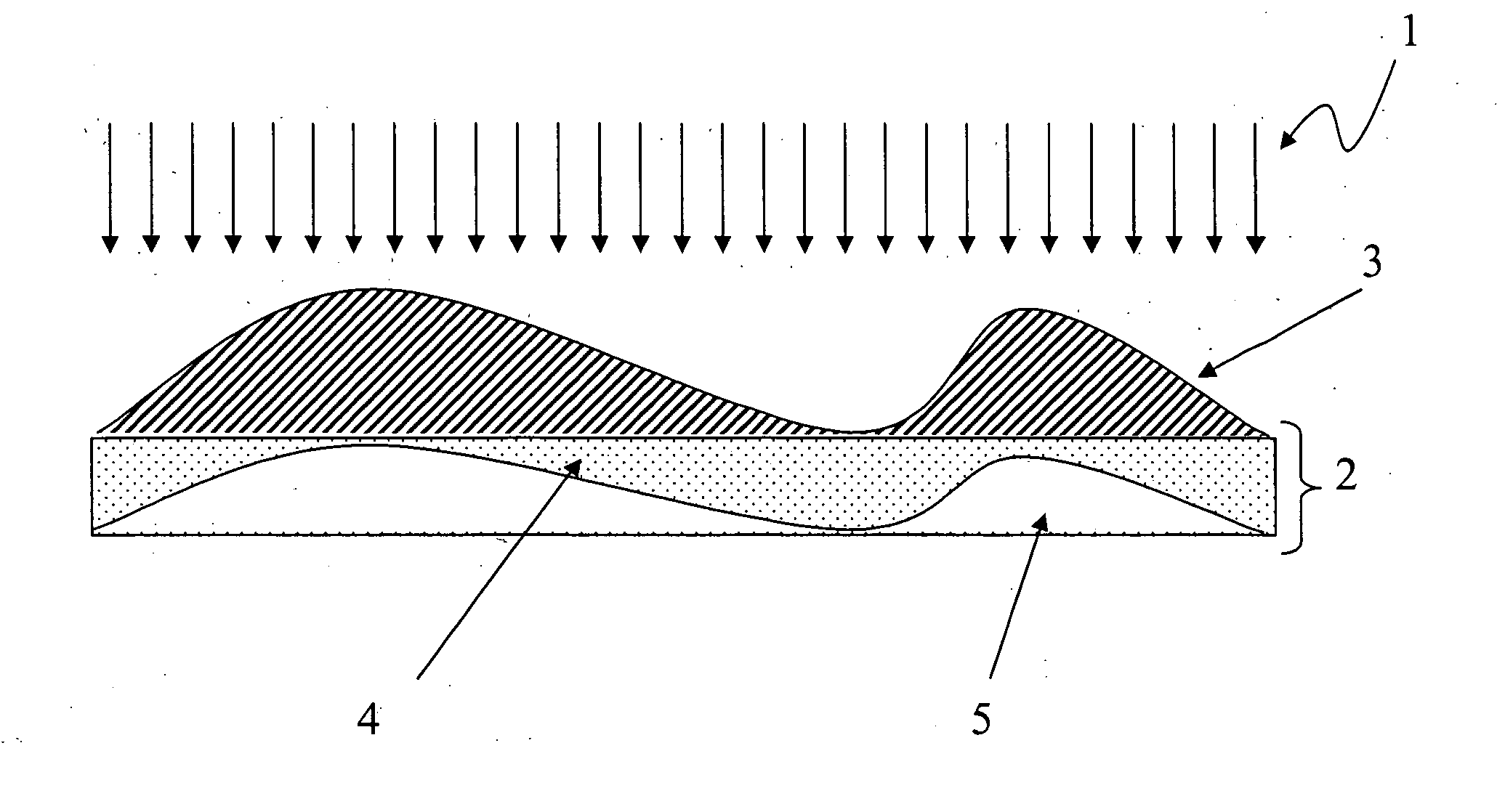
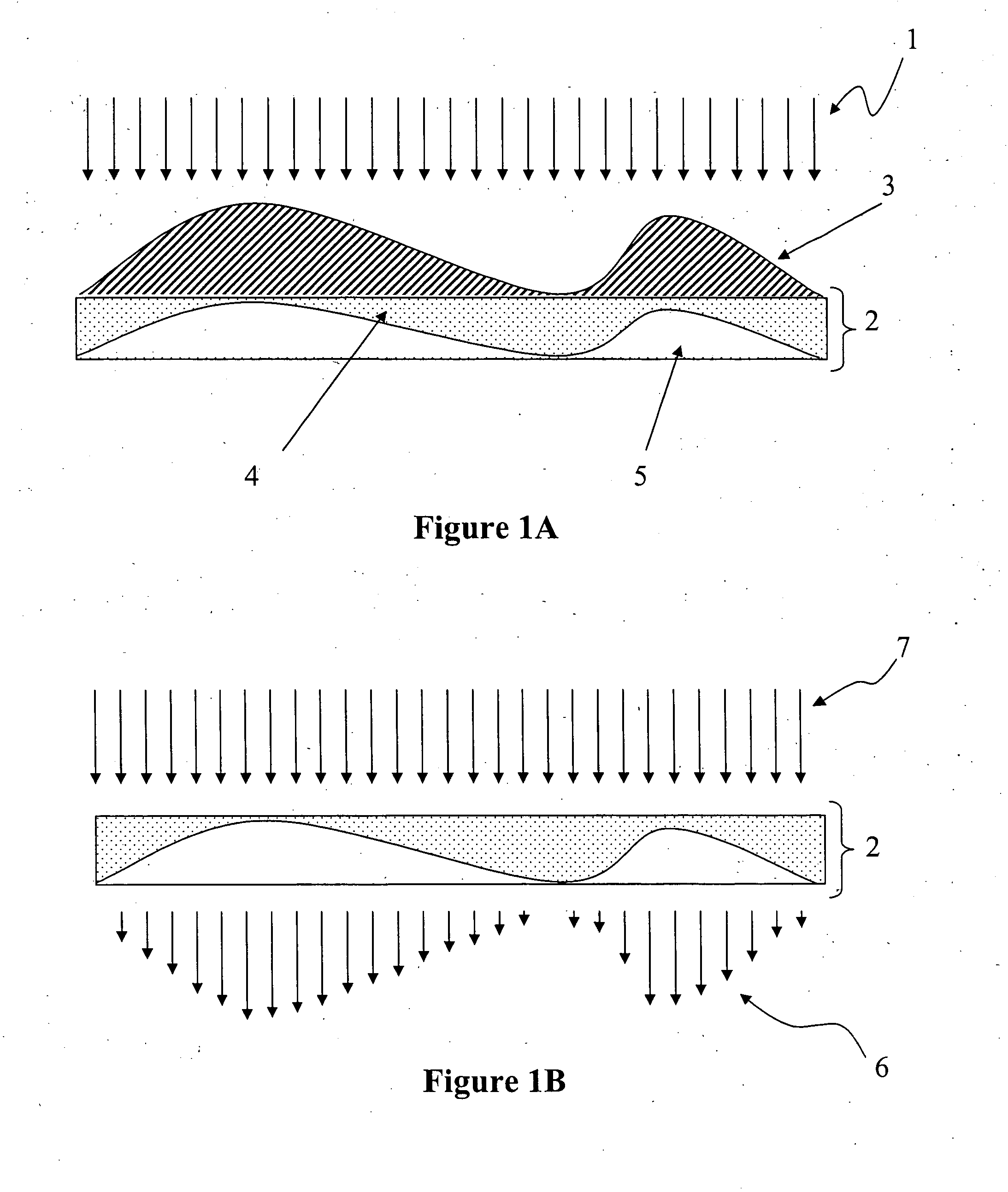
[0038] According to the present invention, absorbing centers are embedded in a transparent mask blank material by ion implantation through a suitable grayscale structure that controls the penetration of the color centers (implanted ions). The implanted ions in the substrate become the color centers which absorb a specific wavelength of light. As a result of this process, the distribution of the absorbing centers over the mask blank surface is modulated corresponding to the grayscale structure to create a grayscale photo mask.

[0039]FIG. 1A illustrates the manner in which ions emitted in a flat ion beam 1 towards a grayscale structure 3 penetrate into a mask blank 2. As shown in FIG. 1A, the penetration depth of the ions in an ion penetrated portion 4 of the mask blank 2 corresponds to a depth of the grayscale structure 3. Particularly, as shown in FIG. 1A, the penetration depth of the ions into the mask blank 2 corresponding to the shallower portions of the grayscale structure 3 is ...


PUM


Abstract

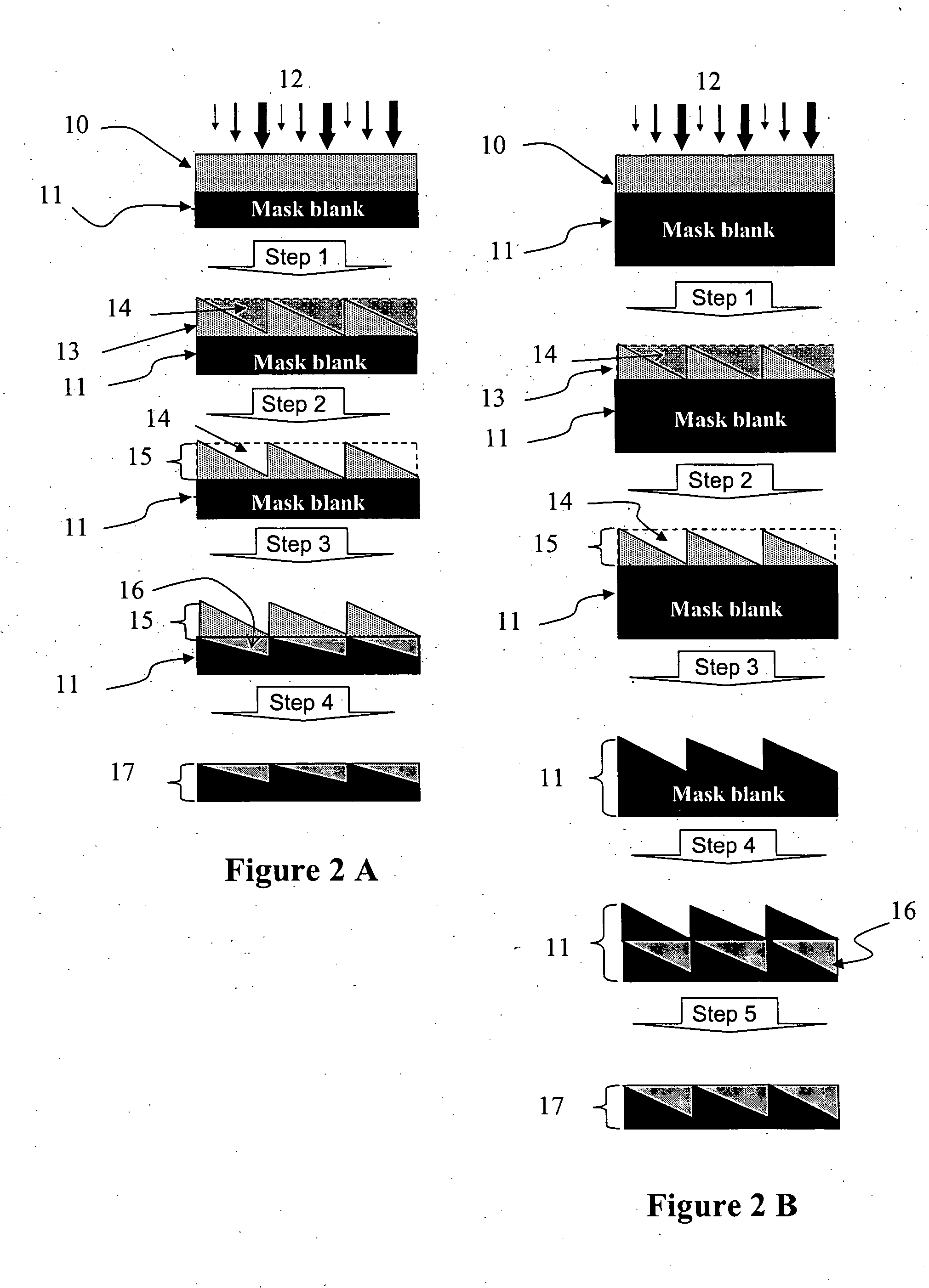
A positive photo resist is provided on a surface of a photo mask blank. Light is then exposed onto the photo resist to form a predetermined pattern of unexposed and exposed portions in the photo-resist. After development, the exposed portions are removed and ions are implanted to obtain a modulated ion density in the photo mask blank. The implanted ions become color centers which absorb a specific wavelength of light and the modulated distribution of the color substrates create the grayscale photo mask. The photo resist structure is finally removed to produce a grayscale photo mask.

Description

BACKGROUND OF THE INVENTION [0001] The present invention is directed to methods for making grayscale photo masks, and methods for making grayscale optical elements using the grayscale photo masks. Examples of the grayscale optical elements include refractive, reflective, and diffractive optical elements such as micro lenses, holograms and gratings. [0002] Newly emerging optical disc formats such as Blu-Ray discs (BD) and High-Density discs (HD) use a blue laser having a 405 nm wavelength in order to focus the laser beam with great precision and tightly pack a large amount of data onto the disc. However, in contrast to the longer wavelengths used for the previous generation of optical discs such as DVD having a 680 nm wavelength, the shorter wavelengths have a lower photo-electron transformation and the reflectance of the reflective coatings provided on the traditional optical elements tend to be insufficient for the shorter wavelength. [0003] As a result of the aforementioned charac...

Claims


Application Information

Patent Timeline
IPC IPC(8): G09B7/00G03C5/00G03F1/00
CPCG03F1/144G03F1/50
Inventor MIZUYAMA, YOSUKELIU, XINBING
Owner PANASONIC CORP
Learn More