
Adaptive transmission rate communication system

a transmission rate and communication system technology, applied in the field of communication methods, can solve the problems of reducing the frame duration, reducing the time diversity of bits in the frame, and fading of the whole fram

Inactive Publication Date: 2006-09-21
KANTERAKIS EMMANUEL
View PDF18 Cites 64 Cited by
  • Summary
  • Abstract
  • Description
  • Claims
  • Application Information

AI Technical Summary

Benefits of technology

"The patent describes a method for adjusting the data rate of transmission on a communication link based on the quality of the underlying channel. This allows for dynamic adjustment of the transmission rate based on channel quality indicators received from the receiver. The method involves transmitting data packets over a number of time slots, with the transmission rate or modulation scheme used in each time slot being changed dynamically based on the channel quality indicators. The receiver uses the information provided in the form of a slot-time indicator and the received signal to determine the per-slot transmission rate. This method enables efficient use of network resources and improved transmission quality."

Problems solved by technology

However, reducing the frame duration is not beneficial for various reasons.
First, reducing the frame duration reduces the time diversity of the bits in that frame.
Reducing diversity amounts to operating in a flat fading channel and therefore, the whole frame is subject to fading.
It is known that reducing the coded packet size the coding gain is also reduced which in turn reduces the overall system capacity.

Method used


Image

  • Adaptive transmission rate communication system
  • Adaptive transmission rate communication system
  • Adaptive transmission rate communication system

Examples


Embodiment Construction

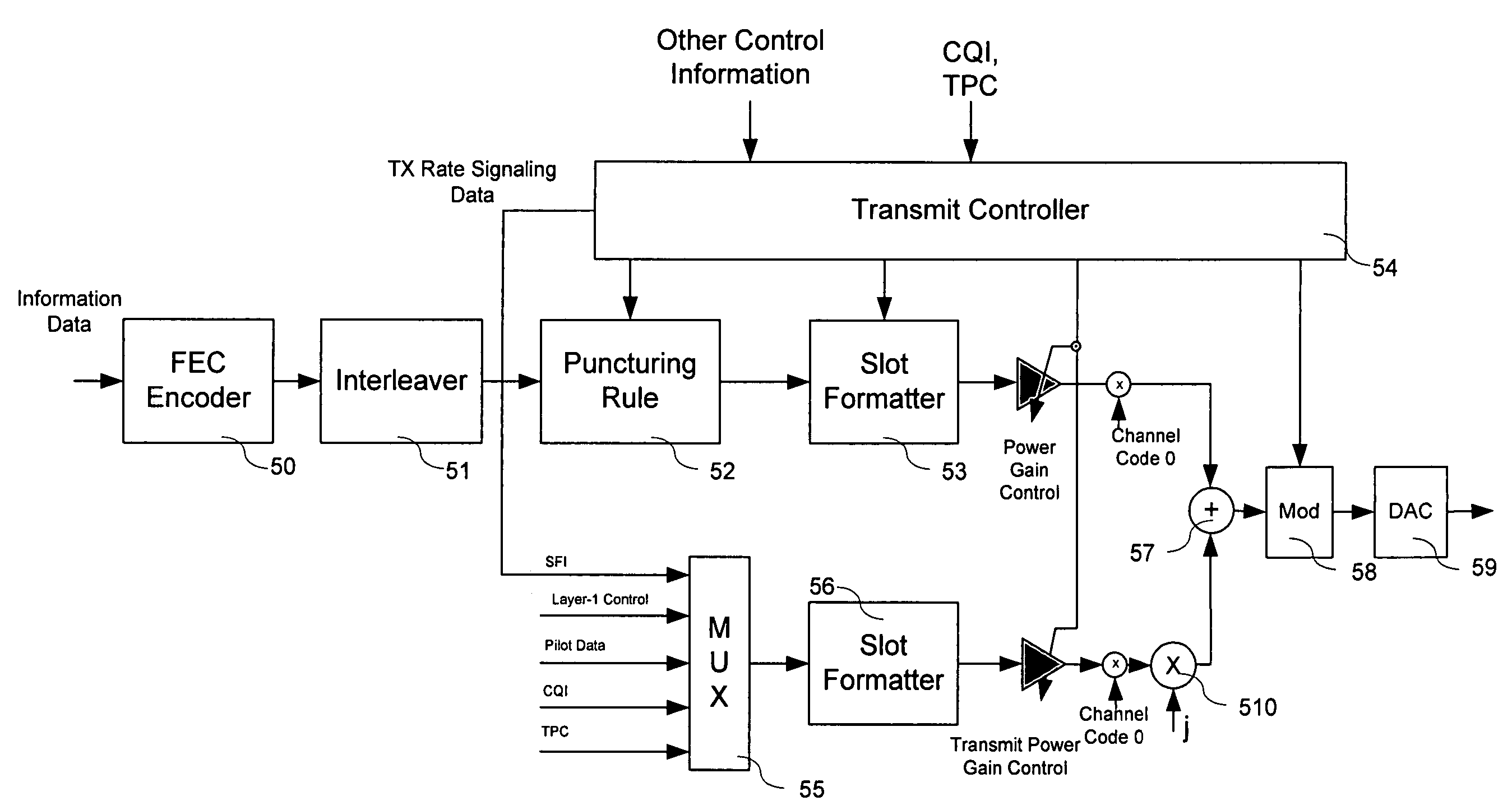
[0015] In FIG. 1, an architectural environment over which the Remote Station or User Equipment (UE) 13, the Base Nodes (NodeBs) 10, 11, 12, and Network controllers 14, 15 could be operating is defined. The disclosed method is applicable for any link where the amount of transmitted energy per transmitted bit for a given grade of service needs to be minimized. The architecture depicted in FIG. 1 is normally used in current wireless cellular systems. The UE is connected to one or more NodeBs 10, 11, 12 through a wireless interface. In the disclosed method, the preferred air-interface is that of DS-SS. Other air-interfaces such as those of TDMA, FDMA, OFDM, OFDMA etc are also applicable by varying the transmission rate based on transmission methods applicable to them. Each NodeB is connected to a Radio Network Controller (RNC) and the RNCs are connected together and to other networks like a High Speed Backbone Network. The RNCs provide management, control and transport to NodeBs which i...


PUM


Abstract

A method is disclosed by which the data rate of the transmission on a communications link is adjusted according to the underlying channel conditions based on a fast Layer-1 feedback Channel Quality Indicator (CQI) control signal received on the return channel. The method enables the system to transmit a data packet of information at different symbol rates during the transmission of a data packet. Each data packet is transmitted over a number of time slots, with the transmission rate or the modulation scheme used in each time slot is changed dynamically during the transmission of the data packet according to channel quality indicators received from the reverse link.

Description

RELATED APPLICATIONS [0001] This application is related and claims the benefits of U.S. provisional patent application APPL No. 60 / 642,918 FILLING DATE Jan. 11, 2005 and entitled “Adaptive transmission rate communication systems”. The content of this provisional application is incorporated herein as reference.BACKGROUND OF THE INVENTION [0002]1.0 Technical Field [0003] The present invention related to an improved communication method for use in communication systems employing a variety of communications techniques such as DS-CDMA and OFDMA. The same technique can be used in other communication techniques where, the energy of the transmitted data needs to be kept to a minimum in order to reduce the amount of interference received by other communication systems operating in the same band at the same time. [0004] 2.0 Background Art [0005] A method by which the transmission data rate is varying from slot to slot according to channel quality information transmitted on the returned link i...

Claims


Application Information

Patent Timeline
Patent Type & Authority Applications(United States)
IPC IPC(8): H04L27/00H03M13/03
CPCH04L1/0003H04L1/0006H04L1/0009H04L1/0026H04L1/0041H04L1/0045H04L1/0068H04L1/1812
Inventor KANTERAKIS, EMMANUEL
Owner KANTERAKIS EMMANUEL
Learn More