Driving system and optical-element driving system
- Summary
- Abstract
- Description
- Claims
- Application Information
AI Technical Summary
Benefits of technology
Problems solved by technology
Method used
Image

Examples
embodiment 1
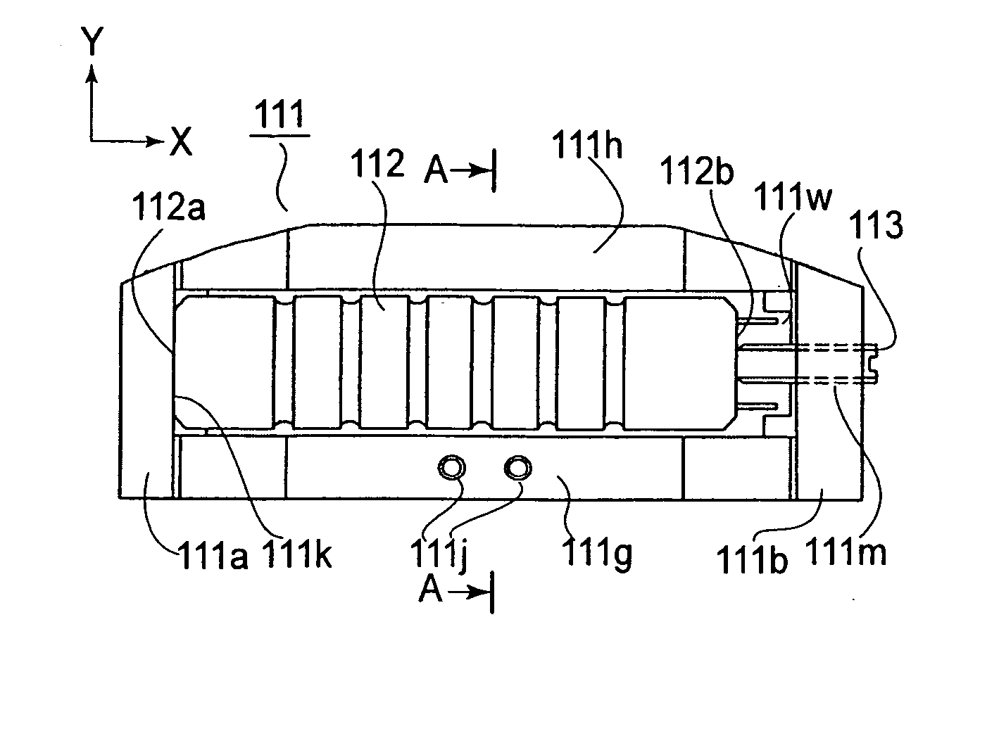
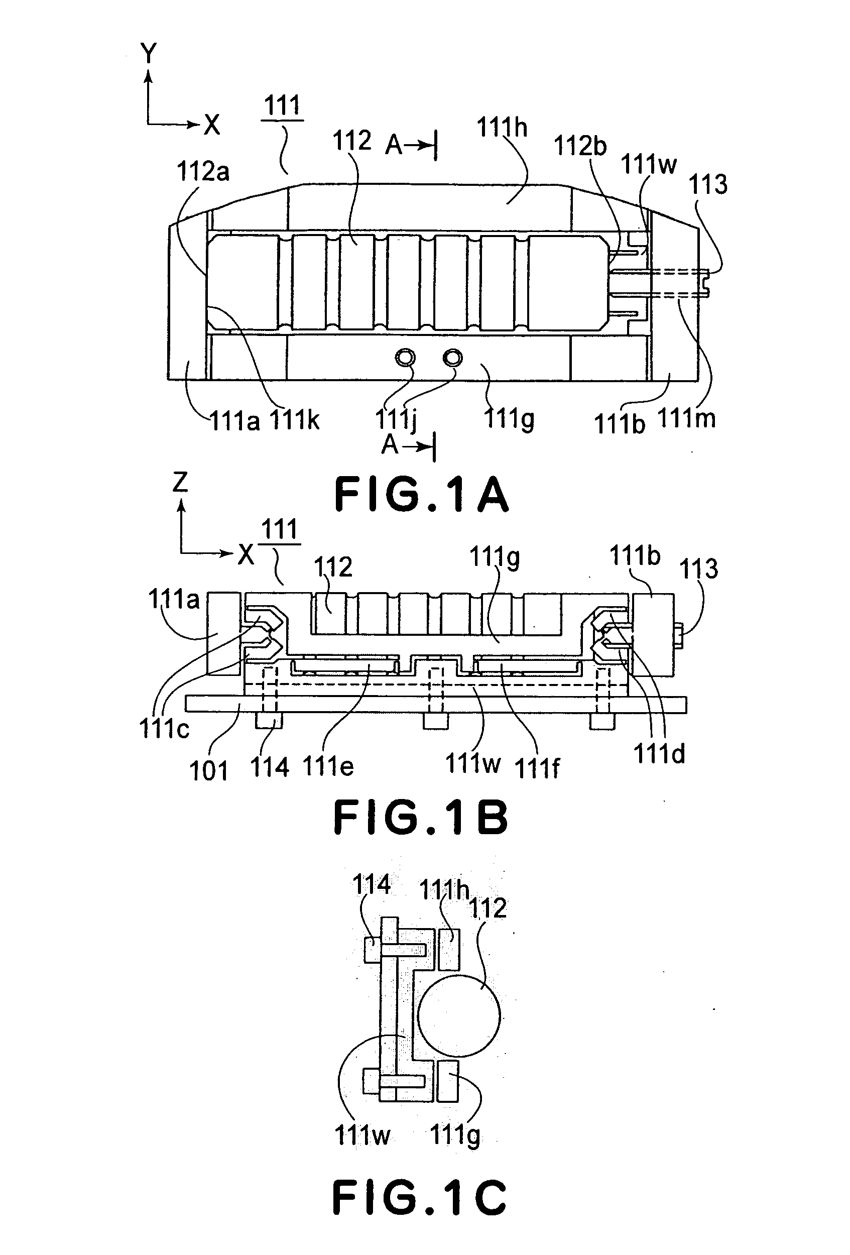
[0037]FIG. 1A through FIG. 6 are illustrations concerning a driving system according to a first embodiment of the present invention.
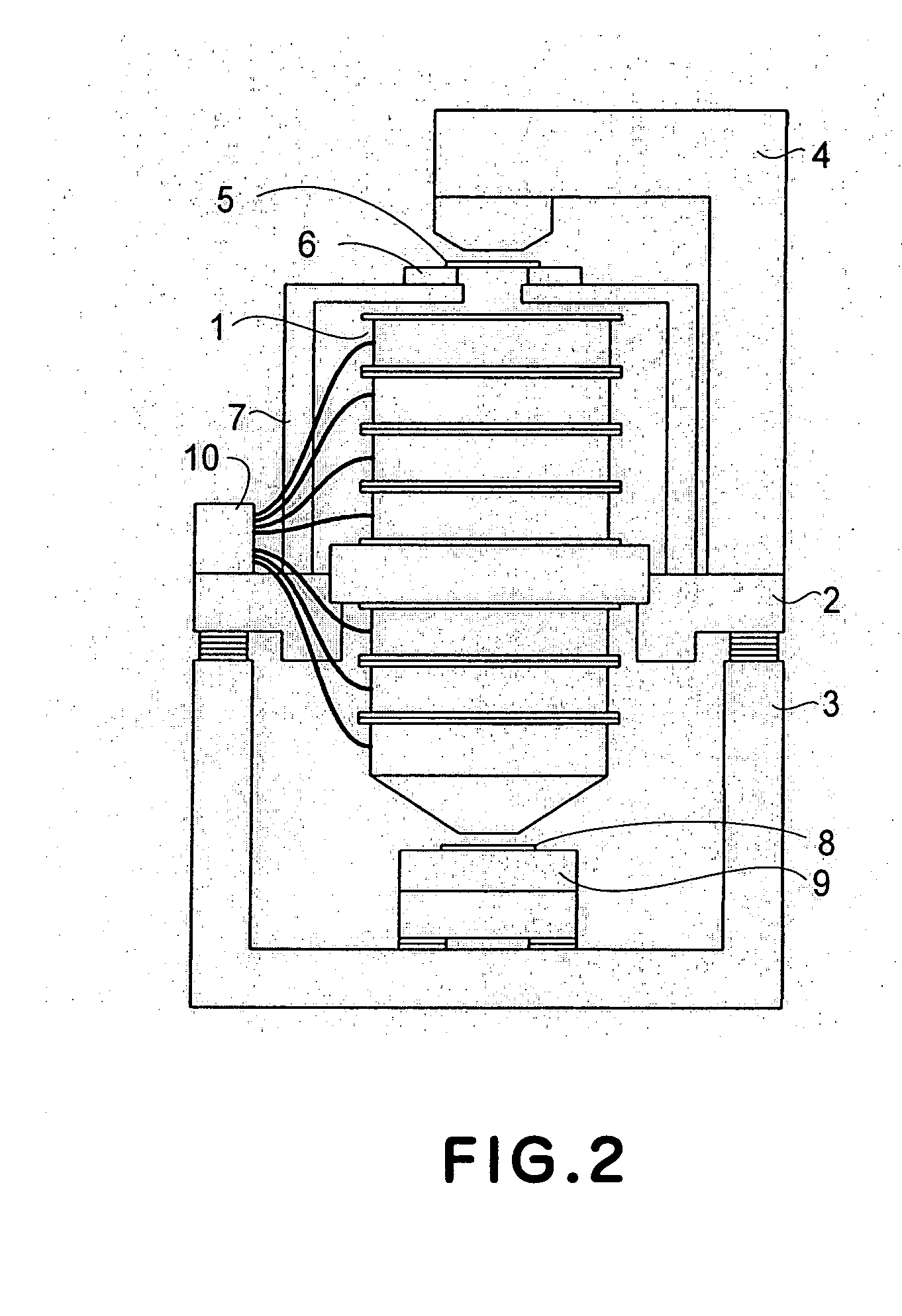
[0038]FIG. 2 is a schematic view that shows a general structure of a semiconductor exposure apparatus to which the present invention is applied.
[0039] This semiconductor exposure apparatus is a scanner type exposure apparatus in which an exposure operation is carried out by scanningly moving a reticle under slit illumination while a semiconductor wafer as well is scanningly moved in synchronism with the reticle scan motion. In FIG. 2, the exposure apparatus has a projection optical system 1 which is equipped with a driving system of the present invention. More specifically, the projection optical system 1 has a plurality of lens units being accumulated, and each unit comprises a lens having a predetermined optical power, a lens driving system for that lens, and a barrel that accommodates the lens and its lens driving system.
embodiment 2
[0088] In the driving system of the first embodiment described hereinbefore, the linkage mechanism of the driving system main assembly 111 has a structure being approximately symmetrical with respect to the X-axis direction. As compared with this, in a driving system according to a second embodiment of the present invention to be described below, the shape in the X direction is made asymmetric. This is to simplify the structure and also to improve the rigidity in the X-axis direction.
[0089]FIG. 8A is a side view of a driving system main assembly according to the second embodiment of the present invention, and FIG. 8B is a schematic view for explaining the operation of the linkage mechanism.
[0090] In FIGS. 8A and 8B, the mechanism comprises a fixed barrel 101, a driving mechanism main assembly 211, a piezoelectric actuator 212 having piezoelectric output ends 212a and 212b, a piezoelectric actuator adjusting screw 213, and mount screws 214. The driving mechanism main assembly 211 i...
embodiment 3
[0117] In the driving systems according to the first and second embodiments described hereinbefore, a direction converting linkage (pantograph type linkage) having an angle of about 45 degrees with respect to the output displacement direction of the actuator is used to convert the direction of the output displacement. As compared therewith, in a third embodiment of the present invention to be described blow, a lever type linkage having an L shape is used to achieve both of reduction of thickness and prevention of unwanted displacement.
[0118]FIGS. 9A and 9B through FIGS. 11 and 11B are illustrations concerning the third embodiment of the present invention.
[0119] Specifically, FIGS. 9A and 9B illustrate details of the driving system of the third embodiment, wherein FIG. 9A is a plan view of it as the same is seen from the above along the optical axis direction of the lens, and FIG. 9B is a side view of the same as seen from the lens center. The X axis, Y axis and Z axis are defined ...
PUM
 Abstract
Description
Claims
Application Information
 - R&D
- Intellectual Property
- Life Sciences
- Materials
- Tech Scout
- Unparalleled Data Quality
- Higher Quality Content
- 60% Fewer Hallucinations
Browse by: Latest US Patents, China's latest patents, Technical Efficacy Thesaurus, Application Domain, Technology Topic, Popular Technical Reports.
© 2025 PatSnap. All rights reserved.Legal|Privacy policy|Modern Slavery Act Transparency Statement|Sitemap|About US| Contact US: help@patsnap.com