
Water detecting system and related method of portable electric device

Inactive Publication Date: 2006-09-21
BENQ CORP
View PDF5 Cites 47 Cited by
  • Summary
  • Abstract
  • Description
  • Claims
  • Application Information

AI Technical Summary

Benefits of technology

[0010] It is an advantage of the claimed invention that the switch disconnects the power supplied by the battery to the electronic circuitry board of the portable electric device if the current detector detects that water has contacted the pair of electric terminals. The electronic circuitry located on the electronic circuitry board will not be short circuited by any water that may reach the electronic circuitry since no power is supplied to the electronic circuitry board. Thus, significant damage to the electronic circuitry of the portable electric device can be avoided.

Problems solved by technology

It is well known that water has the potential to damage electric devices.
When the electric devices are operating at the time that they are exposed to water, the damage can be especially severe.
Water can short circuit electronic circuitry that is in use, causing irreparable damage to the electronic circuitry.
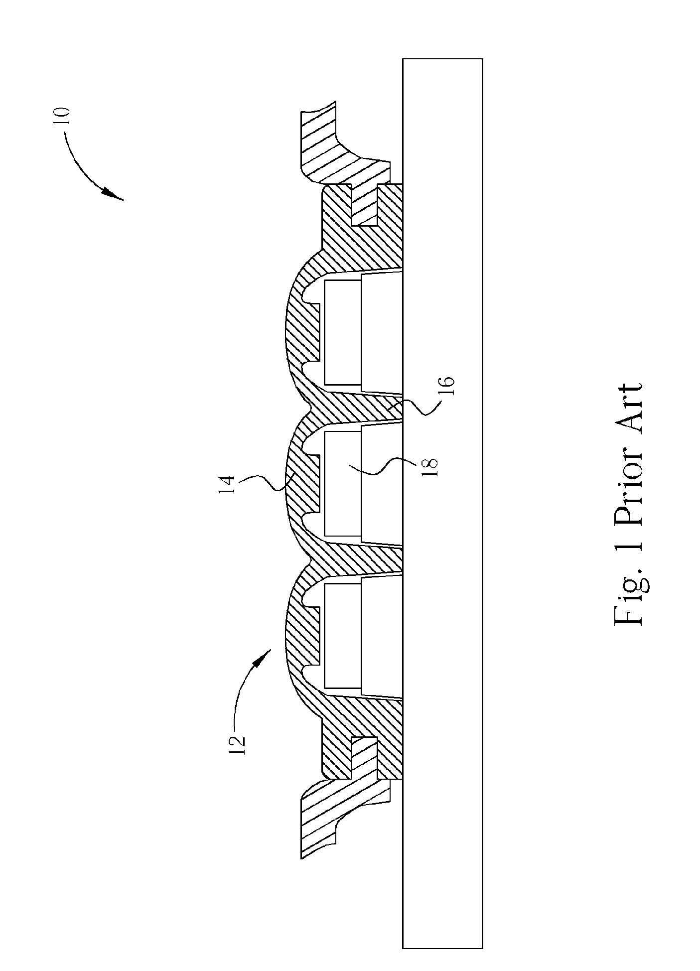
Unfortunately, the water proofing system 10 shown in FIG. 1 is expensive to produce and use of the water proofing system 10 makes it difficult to reduce the size of the electric devices utilizing it.
Moreover, if water is able to enter into the electric devices through other openings or cracks in the housing of the electric device that have not been waterproofed, the electronic circuitry of the electric device may still become damaged.
That is, the water proofing system 10 provides no protection for the electronic circuitry of the electric device when water permeates through the outer housing of the electric device and does not detect that water has entered the outer housing.

Method used


Image

  • Water detecting system and related method of portable electric device
  • Water detecting system and related method of portable electric device
  • Water detecting system and related method of portable electric device

Examples


Embodiment Construction

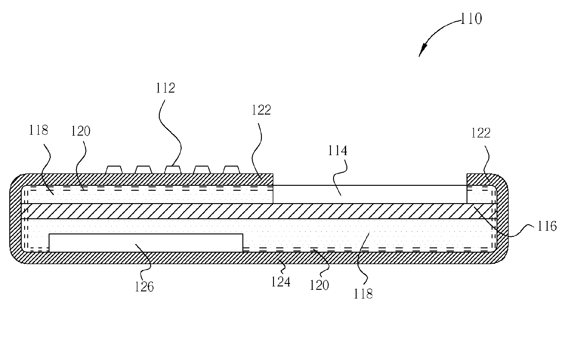
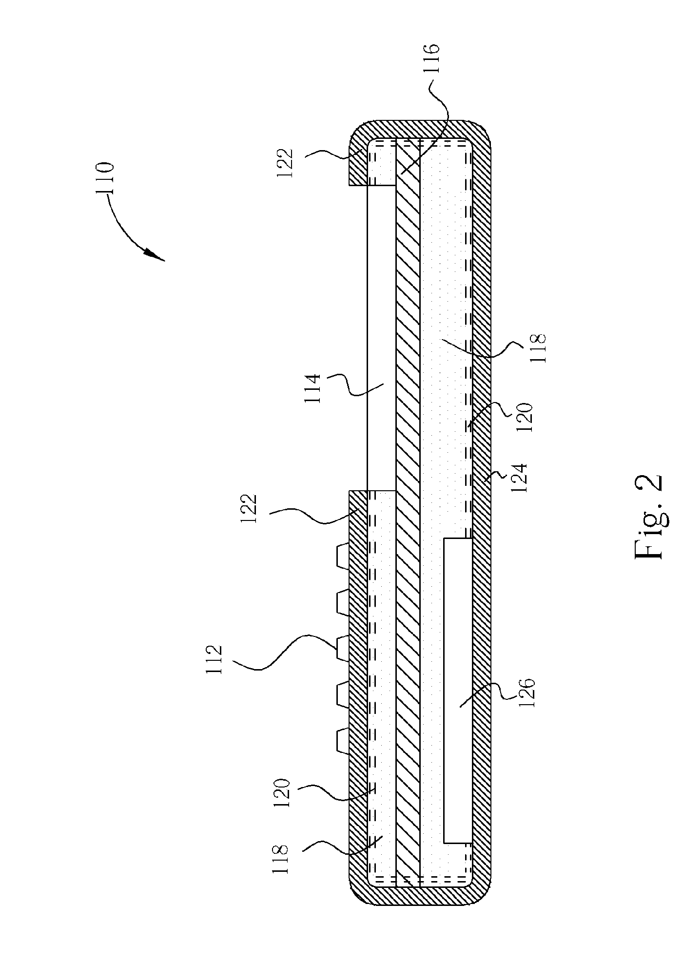
[0015] Please refer to FIG. 2. FIG. 2 is a diagram of a portable electric device 110 utilizing a water detecting system according to the present invention. As an example, the portable electric device 110 shown in FIG. 2 is a mobile phone. However, any portable electric device that has openings through which water may enter the portable electric device can also use the water detecting system of the present invention.

[0016] The portable electric device 110 comprises a plurality of keys 112 disposed on a front housing 122 of the portable electric device 110. A display 114, such as an LCD display, is also formed on an upper surface of the portable electric device 110. A rear housing 124 connects with the front housing 122 for forming an outer housing of the portable electric device 110. A circuit board 116, such as a printed circuit board, is disposed between the front housing 122 and the rear housing 124. The circuit board 116 contains electronic circuitry for controlling operation of...


PUM


Abstract

A water detecting system of a portable electric device comprises a housing, an electronic circuitry board, a battery electrically connected to the electronic circuitry board for providing electrical power to the electronic circuitry board, and at least one pair of electric terminals, the pair of electric terminals comprising one positive terminal and one negative terminal located in close proximity to the positive terminal. When the pair of electric terminals are electrically conducted, a current runs through the pair of electric terminals. The water detecting system also comprises a current detector electrically connected to the pair of electric terminals for detecting if the current running through the pair of electric terminals exceeds a threshold level, and a switch connected to the current detector and the battery for disconnecting the battery from the electronic circuitry board when the current exceeds the threshold level.

Description

BACKGROUND OF INVENTION [0001] 1. Field of the Invention [0002] The present invention relates to a water detecting system for protecting electronic circuitry of a portable electric device when water enters the portable electric device. [0003] 2. Description of the Prior Art [0004] As portable electric devices such as mobile phones, personal digital assistants (PDAs), and notebook computers become a bigger part of people's lives, it also becomes more important to limit the damage caused to these portable electric devices from exposure to water. It is well known that water has the potential to damage electric devices. When the electric devices are operating at the time that they are exposed to water, the damage can be especially severe. Water can short circuit electronic circuitry that is in use, causing irreparable damage to the electronic circuitry. [0005] The traditional defense against water damage is to seal off all openings of the electric device to make the electric device wate...

Claims


Application Information

Patent Timeline
IPC IPC(8): G08B21/00
CPCG01N27/048H04M1/18
Inventor LIU, FENG-CHIWENG, JUNG-TSAN
Owner BENQ CORP
Learn More