
Well logging apparatus for obtaining azimuthally sensitive formation resistivity measurements

a technology of formation resistivity and well logging, which is applied in the direction of well accessories, detection using electromagnetic waves, and borehole/well accessories, etc., can solve the problems of winding, large toroidal core construction, and often problematic use of multiple-turn toroidal transformers, so as to reduce the admittance of the tool body and increase the resistance to alternating current flow

Inactive Publication Date: 2006-09-21
SCHLUMBERGER TECH CORP
View PDF99 Cites 28 Cited by
  • Summary
  • Abstract
  • Description
  • Claims
  • Application Information

AI Technical Summary

Benefits of technology

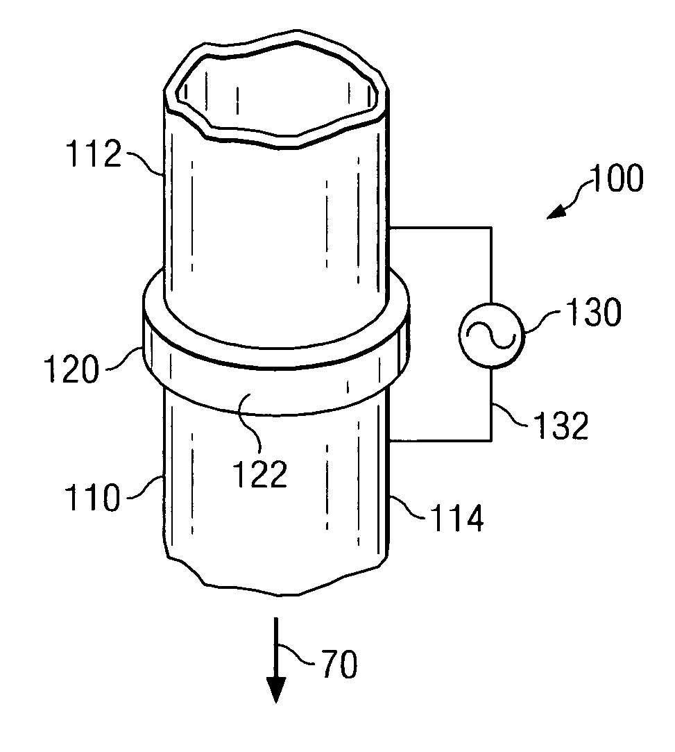
The present invention provides a new method for making azimuthally sensitive resistivity measurements of a subterranean formation. The invention includes a tool body with a magnetically permeable ring and an AC voltage supply, which decreases the resistance to flow of alternating current. The tool body is designed to be coupled with a drill string and can acquire resistivity measurements without removing the drill string from the borehole. The invention also includes current sensing electrodes and a receiver for measuring the AC current. The technical effects of the invention include improved reliability and reduced costs compared to prior art tools.

Problems solved by technology

While prior art LWD resistivity tools have been used successfully in comrnercial drilling applications, utilization of a multiple turn toroidal transformer is often problematic.
Construction and protection of the relatively large toroidal core (e.g., typically having a diameter in the range of 4 to 10 inches) and winding are problematic, especially for use in the demanding downhole environment associated with geophysical drilling.
Mechanical abrasion from cuttings in the drilling fluid and direct hits on the antenna (e.g., from drill string collisions with the borehole wall) have been known to damage wound toroidal core antennas.
Moreover, it is typically expensive to fabricate and maintain wound toroidal core antennas capable of withstanding the above described downhole environment.

Method used


Image

  • Well logging apparatus for obtaining azimuthally sensitive formation resistivity measurements
  • Well logging apparatus for obtaining azimuthally sensitive formation resistivity measurements
  • Well logging apparatus for obtaining azimuthally sensitive formation resistivity measurements

Examples


Embodiment Construction

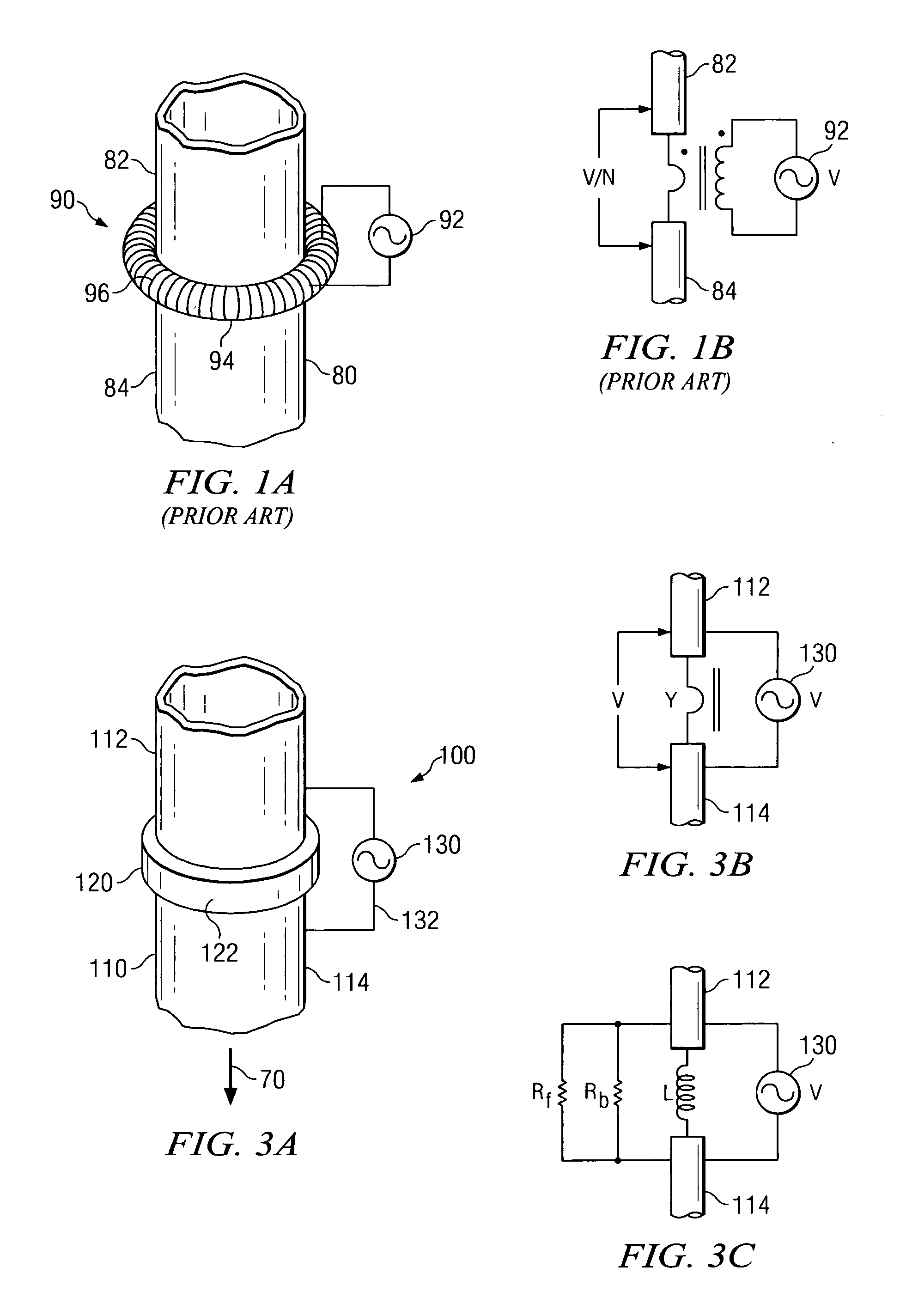
[0026]FIG. 1A schematically illustrates a wound toroidal core antenna 90 deployed about a drill collar 80 as utilized in various prior art downhole resistivity measurement tools. In a typical prior art apparatus, the wound toroidal core antenna 90 includes a toroidal core 94 having multiple windings (N-turns) of insulated wire 96 wrapped thereabout. An AC voltage supply 92 is coupled to the ends of the insulated wire 96. AC current passing through the windings induces a magnetic field in the toroidal core 94 circumferentially about the drill collar 80. The circumferential magnetic field further induces an AC potential difference in the drill collar 80 such that there is a potential difference between upper 82 and lower 84 sides thereof. It will be appreciated that terms used in this disclosure such as “upper” and “lower” are intended merely to show relative positional relationships in the described exemplary embodiments and are not limiting of the invention in any way. As described ...


PUM


Abstract

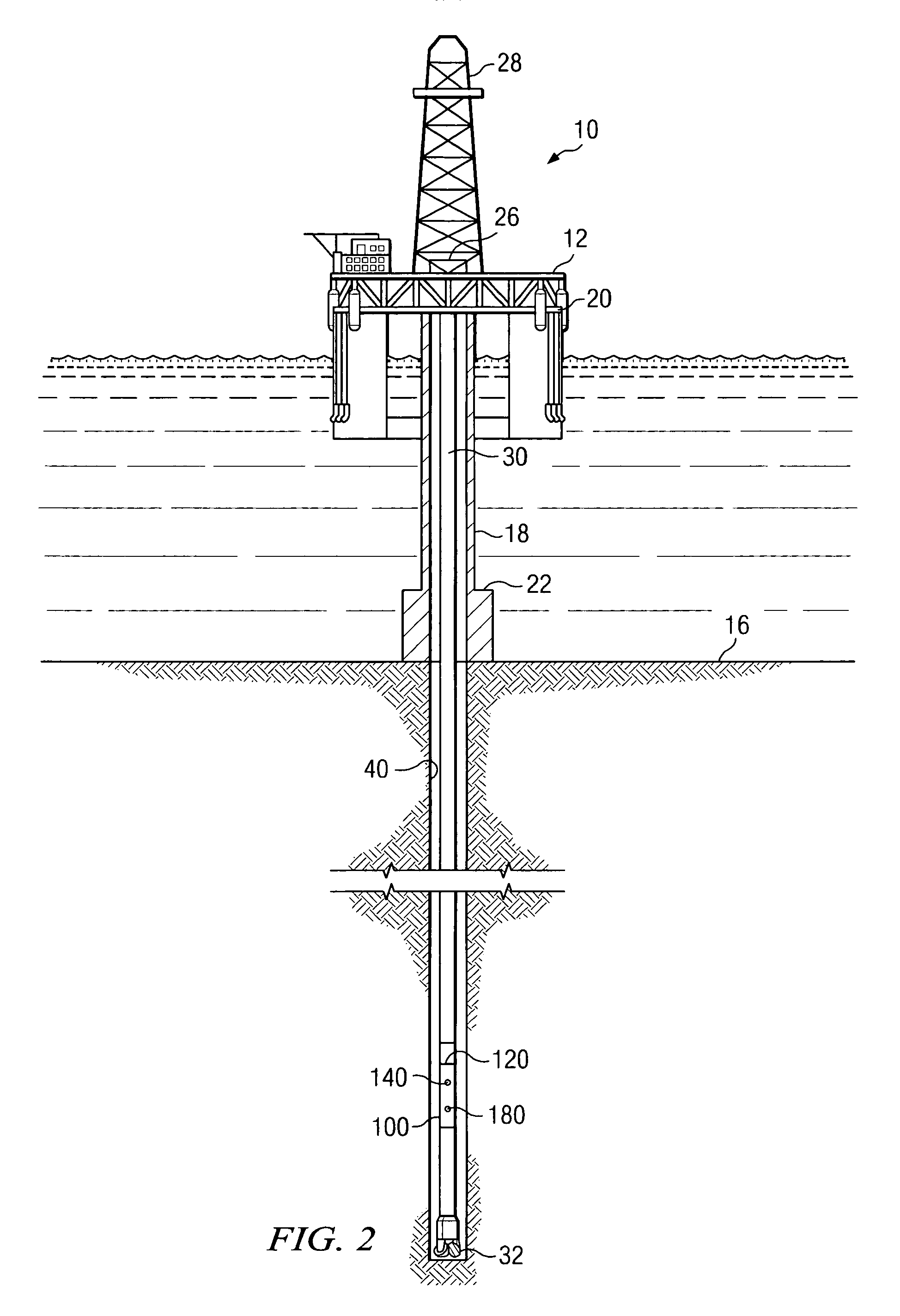
An apparatus for making azimuthally sensitive resistivity measurements of a subterranean formation is disclosed. The apparatus includes a magnetically permeably ring deployed about an electrically conductive tool body. An AC voltage supply is coupled to the tool body on opposing sides of the magnetically permeable ring, with at least one connecting conductor crossing outside the ring. Exemplary embodiments of this invention may further include one or more current sensing electrodes deployed in and electrically isolated from an outer surface of the tool body and may be utilized to make azimuthally resolved formation resistivity measurements

Description

FIELD OF THE INVENTION [0001] The present invention relates generally to an apparatus for logging a subterranean borehole. More specifically, this invention relates to an apparatus, such as a logging while drilling tool, for making azimuthally sensitive resistivity measurements of a subterranean formation. BACKGROUND OF THE INVENTION [0002] The use of electrical measurements in prior art downhole applications, such as logging while drilling (LWD), measurement while drilling (MWD), and wireline logging applications is well known. One such electrical measurement technique is utilized to determine a subterranean formation resistivity, which, along with formation porosity measurements, is often used to indicate the presence of hydrocarbons in the formation. For example, it is known in the art that porous formations having a high electrical resistivity often contain hydrocarbons, such as crude oil, while porous formations having a low electrical resistivity are often water saturated. It ...

Claims


Application Information

Patent Timeline
Patent Type & Authority Applications(United States)
IPC IPC(8): G01V3/08
CPCG01V3/24G01V3/20
Inventor MOORE, ROBERT A.
Owner SCHLUMBERGER TECH CORP
Learn More