
DC/DC converter

a converter and converter technology, applied in the direction of dc-dc conversion, power conversion system, instruments, etc., can solve the problems of uneven loss, circuit complexity, and inability to balance the electric current in the converter,

Inactive Publication Date: 2006-09-21
SANKEN ELECTRIC CO LTD
View PDF4 Cites 17 Cited by
  • Summary
  • Abstract
  • Description
  • Claims
  • Application Information

AI Technical Summary

Benefits of technology

[0015] An object of the present invention is to provide a step-up DC / DC converter with which the ripple current which flows through a smoothing capacitor can be reduced, and the circuit can be simplified, and which DC / DC converter can thus be downsized.
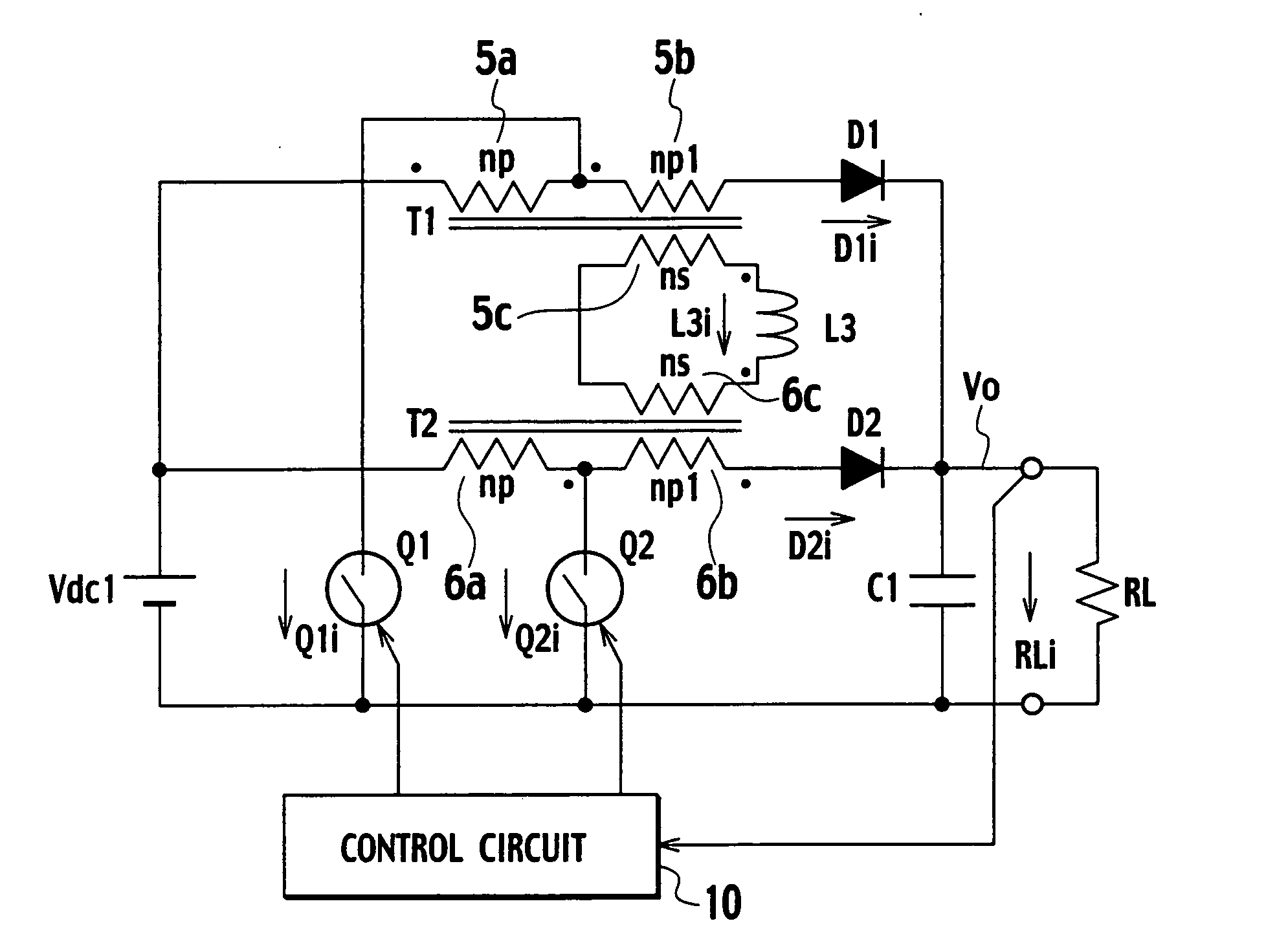
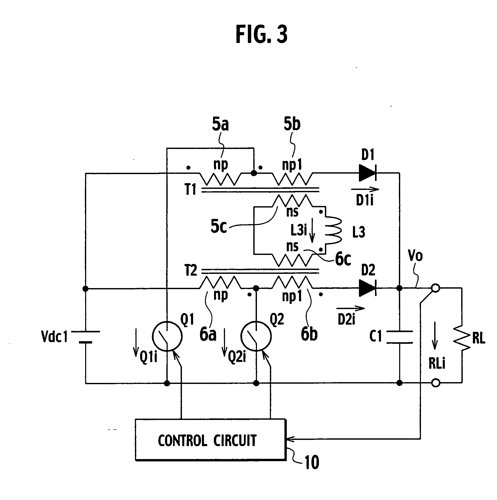
[0019] On the other hand, once the second switch is turned on, an electric current flows through the primary winding of the second transformer. A voltage is then generated across the secondary winding of the second transformer, and energy is stored in the reactor. The energy stored in the reactor causes a voltage to be generated across the primary and additional windings of the first transformer via the secondary winding of the first transformer, and is thus returned to the smoothing capacitor via the first diode (or the third switch in the second mode of the present invention). In other words, the frequency at the reactor as an energy storage element is doubled, so that the reactor can be downsized. In addition, the current balance between the two converters can be achieved.
[0021] With the present invention, by adjusting the additional winding ratio of the transformer, the duty factor of each of the switches can be reduced, and the ripple current which flows through the smoothing capacitor can therefore be reduced. In addition, it is possible to downsize the smoothing capacitor, to reduce the loss, and to achieve high efficiency.
[0023] With the present invention, by using the core having three legs, the first and second transformers and the reactor are integrated, so that the circuit can be simplified, and the DC / DC converter can be further downsized and improved in efficiency.
[0025] With the present invention, the coupling between the first and second coils is excellent, and almost all of the magnetic flux generated by these coils passes through the magnetic shunt. For this reason, the inductance can be adjusted over a wide range by changing the gap of the magnetic shunt. Accordingly, for an application in which a large peak current flows, the DC / DC converter can be used without core saturation by setting the gap large.

Problems solved by technology

In addition, if a perfect symmetry between the two converters inclusive of the circuit wiring cannot be maintained, the electric currents in these converters cannot be balanced, and the uneven loss will be caused.
Moreover, a correction circuit or the like which carries out correction so that the electric currents in the converters are balanced, becomes necessary, which has resulted in a disadvantage that the circuit becomes complicated.

Method used


Image

  • DC/DC converter
  • DC/DC converter
  • DC/DC converter

Examples


first embodiment

[0041]FIG. 3 is a circuit configuration diagram of a DC / DC converter of a first embodiment. The DC / DC converter shown in FIG. 3 is a converter for boosting the voltage of a DC power supply. The DC / DC converter includes the DC power supply Vdc1, a transformer T1 (corresponding to the first transformer of the present invention), a transformer T2 (corresponding to the second transformer of the present invention), a reactor L3 (corresponding to the reactor of the present invention), a switch Q1 (corresponding to the first switch of the present invention), a switch Q2 (corresponding to the second switch of the present invention), a diode D1 (corresponding to the first diode of the present invention), a diode D2 (corresponding to the second diode of the present invention), a smoothing capacitor C1, and a control circuit 10.

[0042] The transformer T1 has a primary winding 5a (np turns), an additional winding 5b (np1 turns) connected to the primary winding 5a in series, and a secondary wind...

second embodiment

[0062]FIG. 5 is a circuit configuration diagram of a DC / DC converter of a second embodiment. The DC / DC converter shown in FIG. 5 is different from the DC / DC converter shown in FIG. 3 in the following point. That is, the diode D1 is connected between the primary winding 5a and the additional winding 5b of the transformer T1, and the diode D2 is connected between the primary winding 6a and the additional winding 6b of the transformer T2.

[0063] Since an operation of the DC / DC converter of the second embodiment thus configured is similar to that of the DC / DC converter shown in FIG. 3, similar effects can be obtained.

[0064] In addition, since the switch Q1 and the diode D1 are provided closely, and the switch Q2 and the diode D2 are provided closely, the switches Q1 and Q2 can be integrated with the diodes D1 and D2, respectively. Accordingly, the circuit can be modularized or integrated into an IC.

third embodiment

[0065]FIG. 6 is a circuit configuration diagram of a DC / DC converter of a third embodiment. The DC / DC converter shown in FIG. 6 is characterized in that, in the DC / DC converter shown in FIG. 3, the diode D1 is replaced with a switch Q3 (corresponding to the third switch of the present invention) comprised of a MOSFET or the like, and the diode D2 is replaced with a switch Q4 (corresponding to the fourth switch of the present invention) comprised of a MOSFET or the like.

[0066] A control circuit 10a turns on and off the switches Q1 and Q2 with a phase difference of 180°, turns on and off the switches Q3 and Q1 complementarily, and turns on and off the switches Q4 and Q2 complementarily.

[0067] Since an operation of the DC / DC converter of the third embodiment is similar to that carried out in accordance with the timing chart shown in FIG. 4, detailed description of the operation will be omitted. The timing chart of the third embodiment can be obtained by replacing the electric current...


PUM


Abstract

A DC / DC converter according to the present invention includes a first switch connected to both ends of the DC power supply through a primary winding of a first transformer, a second switch connected to both ends of the DC power supply through a primary winding of a second transformer, a first series circuit connected between a node to which the primary winding of the first transformer and one end of the first switch are connected, and another end of the first switch, the first series circuit including a first diode, a smoothing capacitor, and an additional winding of the first transformer, which is connected to the primary winding of the first transformer in series, a second series circuit connected between a node to which the primary winding of the second transformer and one end of the second switch are connected, and another end of the second switch, the second series circuit including a second diode, the smoothing capacitor, and an additional winding of the second transformer, which is connected to the primary winding of the second transformer in series, a reactor connected to both ends of a series circuit in which a secondary winding of the first transformer and a secondary winding of the second transformer are connected in series, and a control circuit which turns on and off the first and second switches with a phase difference of half a cycle.

Description

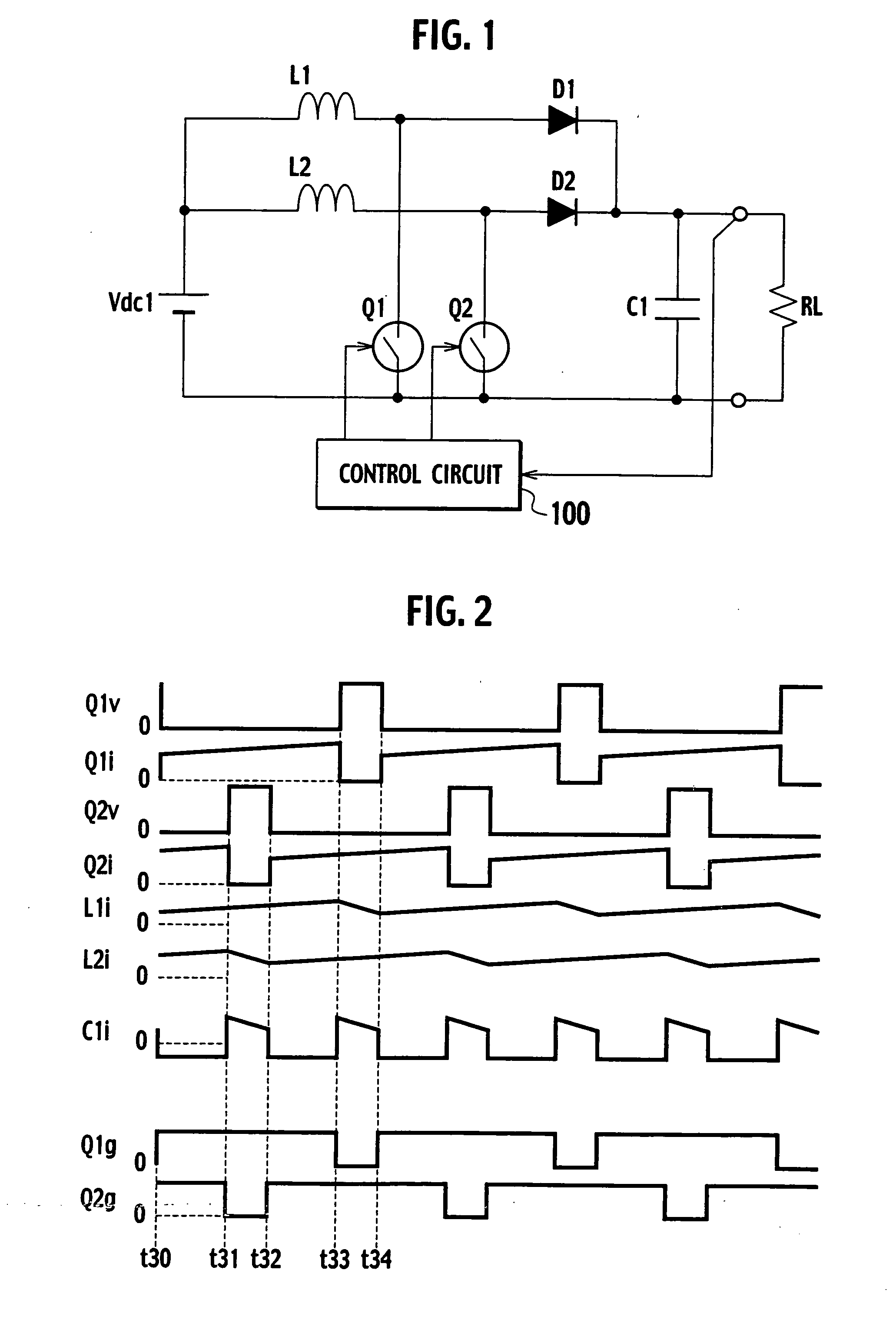
BACKGROUND OF THE INVENTION [0001] 1. Field of the Invention [0002] The present invention relates to high-capacity, step-up DC / DC converters, and particularly to technologies for downsizing the same. [0003] 2. Description of the Related Art [0004]FIG. 1 is a circuit configuration diagram of a conventional DC / DC converter. This DC / DC converter is described in JP2002-10632 A. The DC / DC converter shown in FIG. 1 is a step-up converter for large output current. In order to reduce the ripple current which flows through a smoothing capacitor C1, two converters are connected in parallel in the DC / DC converter, the converters operating with a 180° phase shift. [0005] A switch Q1 comprised of a MOSFET or the like is connected to both ends of a DC power supply Vdc1 through a reactor L1. A switch Q2 comprised of a MOSFET or the like is connected to both ends of the DC power supply Vdc1 through a reactor L2. A series circuit including a diode D1 and the smoothing capacitor C1 is connected betwe...

Claims


Application Information

Patent Timeline
Patent Type & Authority Applications(United States)
IPC IPC(8): G05F1/00
CPCH02M1/14H02M3/1584H02M2001/0064H02M2003/1586H02M1/0064H02M3/1586
Inventor TSURUYA, MAMORU
Owner SANKEN ELECTRIC CO LTD
Learn More