Connection element for the transport of gaseous, liquid or solid materials

a technology of connection elements and gaseous liquids, applied in the direction of pipe joints, pipe elements, couplings, etc., can solve the problem that the tubular coupling cannot be released

Inactive Publication Date: 2006-09-21
SIEMENS AG
View PDF23 Cites 12 Cited by
  • Summary
  • Abstract
  • Description
  • Claims
  • Application Information

AI Technical Summary

Benefits of technology

[0003] The object on which the invention is based is therefore, to provide a connection element for the transport of gaseous, liquid or solid materials, in which the insertion forces can be kept relatively low, while at the same time an automatic release can be avoided. The object on which the invention is based is, furthermore, to provide a use for the connection element.
[0005] In a preferred embodiment of the invention, the first seal is arranged between the first step and a cross-sectional narrowing. The cross-sectional narrowing may in this case, for example, be of bead-like design. This advantageously makes mounting easier during the assembly of the connection element, since the first seal can be fixed in the tubular coupling relatively simply.
[0006] In a further preferred embodiment of the invention, there is provision for the first outside diameter D1 of the coupling in the region between the at least one clearance and the one end to amount to 1.1 to 1.15 times the second outside diameter D2 of the coupling in the region between the at least one clearance and the other end. The advantageous reduction in the second outside diameter D2, as compared with the first outside diameter D1, makes it easier for the snap ring to be pushed onto the tubular coupling, since the snap ring, when being pushed on in this way, has to be pushed over the first projection of the tubular coupling, and in this case, at this point, there is a slight upsetting of the tubular coupling which is assisted by the slight reduction in material. The connection element can thus be premounted more easily.

Problems solved by technology

In the connected state, however, the snap ring and the tubular coupling cannot be released from one another in the direction of the longitudinal axis, and therefore the connection element at the same time ensures a reliable connection.

Method used


Image

  • Connection element for the transport of gaseous, liquid or solid materials
  • Connection element for the transport of gaseous, liquid or solid materials
  • Connection element for the transport of gaseous, liquid or solid materials

Examples


Embodiment Construction

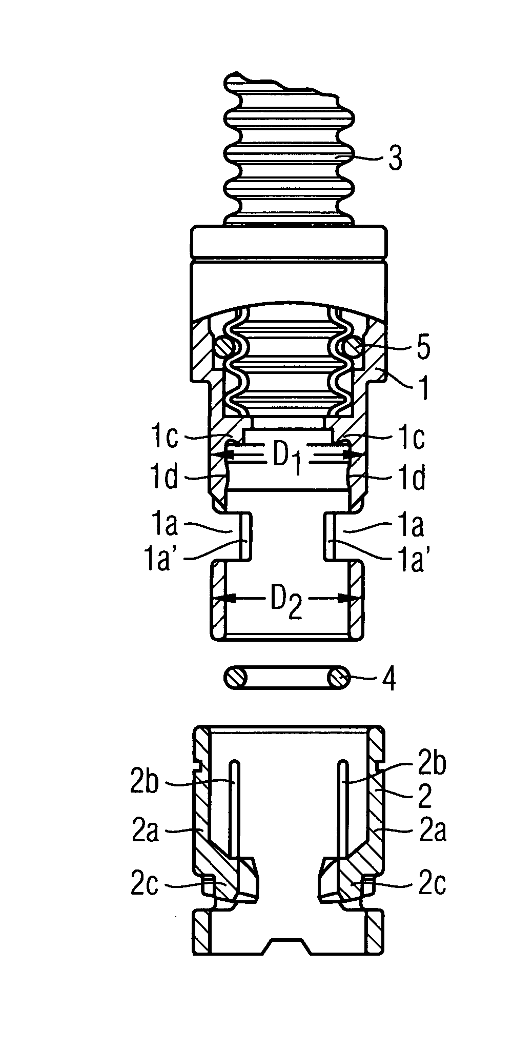
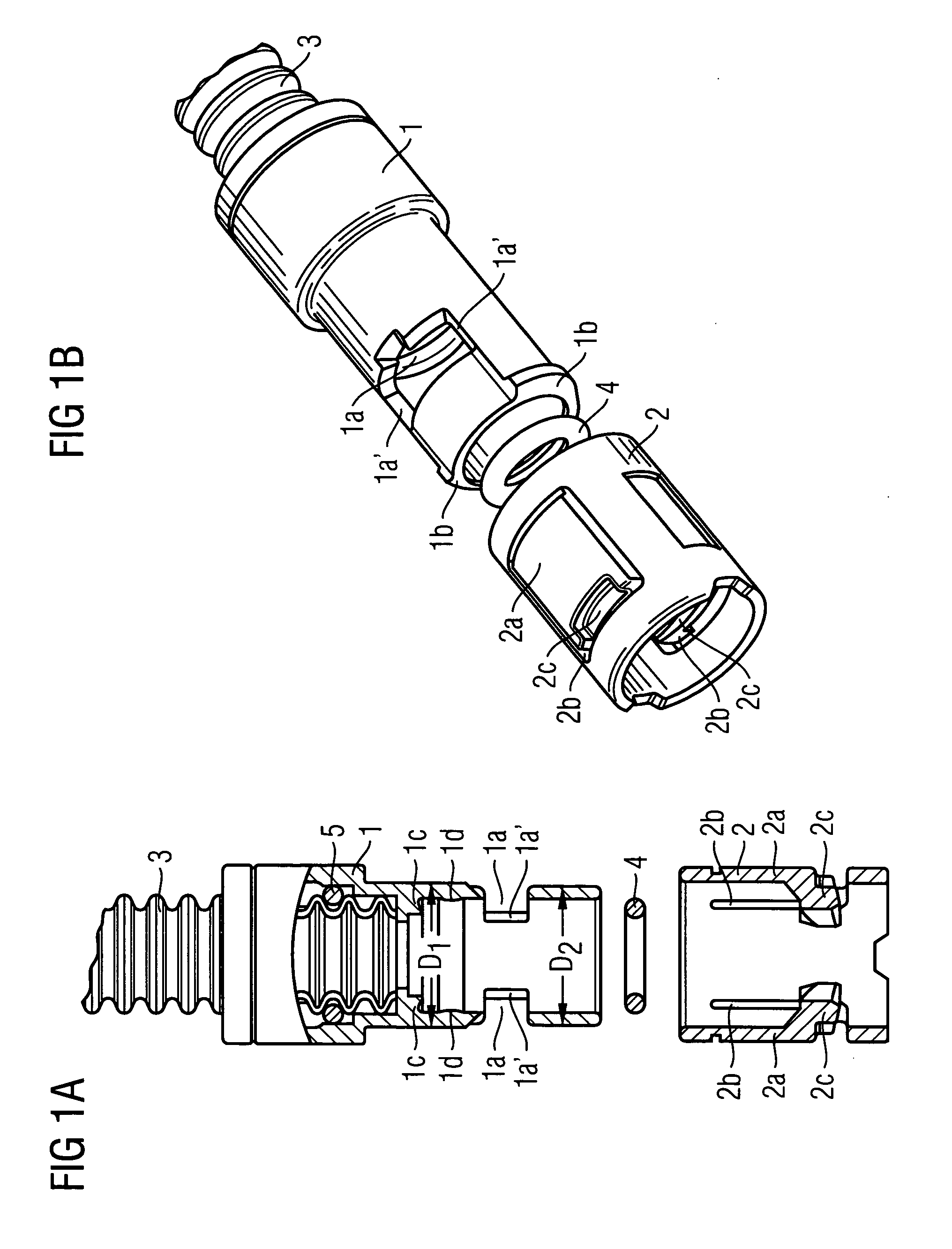
[0014]FIGS. 1a), b) illustrate the connection element for the transport of gaseous, liquid or solid materials respectively in longitudinal section and three-dimensionally in the form of an exploded drawing. The connection element consists of a tubular coupling 1 which is connected on the inside at one end to a hose 3 which, in the present case, is designed as a corrugated hose. Sealing off in this case takes place by means of the arrangement of a second seal 5. The tubular clutch 1 has, on its side facing away from the hose 3, two clearances 1a, of which the lateral edges. 1a′ running parallel to the longitudinal axis of the tubular coupling 1 run, in the cross section of the respective clearance 1a, so as to widen conically with respect to one another from the inside outward. Two first projections 1b are arranged on the outside at the other end of the tubular coupling 1 and, in the assembled state (not illustrated), bear against one end face of a snap ring 2 which is then arranged ...


PUM


Abstract

The connection element includes a tubular coupling which is connected on the inside at one end to a hose which has, on its side facing away from the hose , at least one clearance, of which the lateral edges running parallel to the longitudinal axis of the tubular coupling run, in the cross section of the respective clearance, so as to widen conically with respect to one another from the inside outward. The tubular coupling has at the other end, on the outside, at least one first projection which bears against one end face of a snap ring which is arranged between the at least one projection and the one end of the coupling, around the coupling on the outside.

Description

BACKGROUND OF THE INVENTION [0001] The invention relates to a connection element for the transport of gaseous, liquid or solid materials and to the use of the connection element. [0002] Connection elements for the transport of gaseous, liquid or solid materials are known. DE 103 22 972 A1 describes a corresponding connection element consisting of a tubular coupling which has on the inside a first clearance running cylindrically, in which a corrugated hose is arranged and which has a cylindrically running second clearance which is contiguous to the first clearance and in which an annular seal with respect to the first clearance is arranged and a spreading ring is arranged adjacently to the annular seal, the spreading ring having on the outside a first projection which points toward the coupling and which engages into a continuous groove arranged in the second clearance, and in which the spreading ring is in engagement with a projection pointing toward the corrugated hose and the annu...

Claims


Application Information

Patent Timeline
Patent Type & Authority Applications(United States)
IPC IPC(8): F16L39/00
CPCF16L25/0045F16L37/0985
Inventor DISCHER, THOMASMARTIN, UWESTANGE, RUEDIGERWERNER, THOMAS
Owner SIEMENS AG
Why Eureka
Try Eureka