
Helical implant

a technology of implants and helices, applied in the field of helical implants, can solve the problems of inconvenient mounting of prostheses in the mouth, damage to healthy teeth, and contact with foreign materials, and achieve the effect of restricting stress concentration

Inactive Publication Date: 2006-09-14
SUL YOUNG TAEK
View PDF18 Cites 18 Cited by
  • Summary
  • Abstract
  • Description
  • Claims
  • Application Information

AI Technical Summary

Benefits of technology

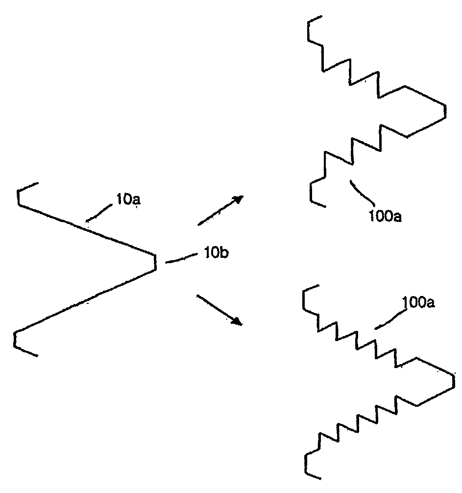
[0013] The present invention has been made to solve the above problems, and it is an object of the present invention to provide a helical implant, which is formed with a micro-pattern on thread inclines of the helical implant, so that a contact area and a engaging force between the implant and the jaw bone can be increased, and so that stress concentration can be restricted, thereby dispersing a physiological load.

Problems solved by technology

However, the bridge operation has a problem in that damage of the healthy tooth is accompanied with the grinding of the healthy tooth near the extracted tooth.
Further, the partial or total prosthesis operation has problems in that there are inconvenience of mounting the prosthesis in the mouth, contact with foreign materials, and damage to the healthy tooth, which contact the prosthesis.
However, the conventional implant has problems in that due to smoothness of the thread inclines of the anchoring member, a contact area between the screw thread and the bottom of the thread is limited, thereby reducing a mechanical engaging force between the implant and the bone, and in that the cavity of the anchoring member causes reduction in specific volume, lowering a supporting force of the implant.
Further, there are problems in that due to the rotation of the cutting edge, adjoining jaw bone tissue is also damaged, and in that a contact gap can be formed between the implant and the jaw bone tissue, which directly influences the success ratio of the implant operation.

Method used


Image

  • Helical implant
  • Helical implant
  • Helical implant

Examples


Embodiment Construction

[0025] Now, preferred embodiments of the present invention will be described in detail with reference to the accompanying drawings so that those skilled in the art may easily understand and repeat the present invention. The accompanying drawings are provided as an example for illustrating the preferred embodiments of the present invention in detail, and the scope of the present invention is not limited by the drawings and the description referring to the drawings.

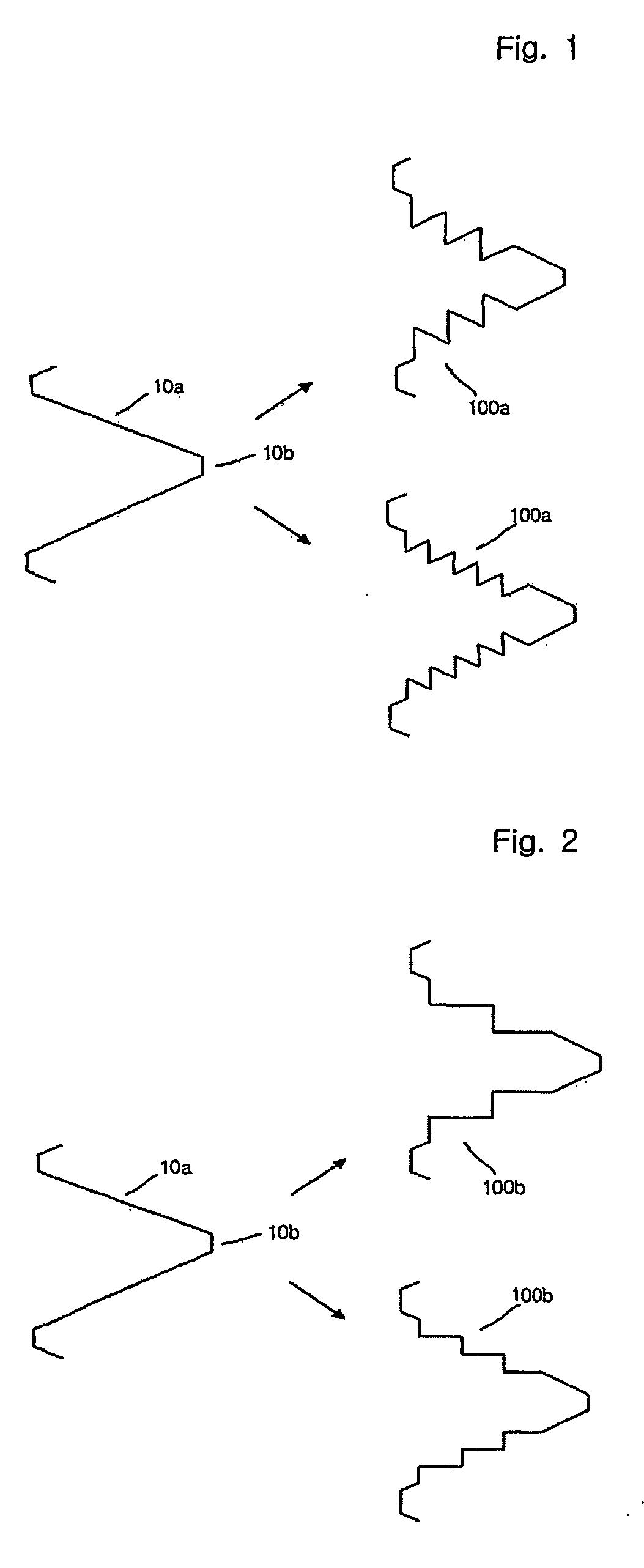
[0026] A helical implant according to the present invention is formed with threads on the outer surface thereof, and each of the threads has thread inclines formed with one or more recesses or protrusions thereon.

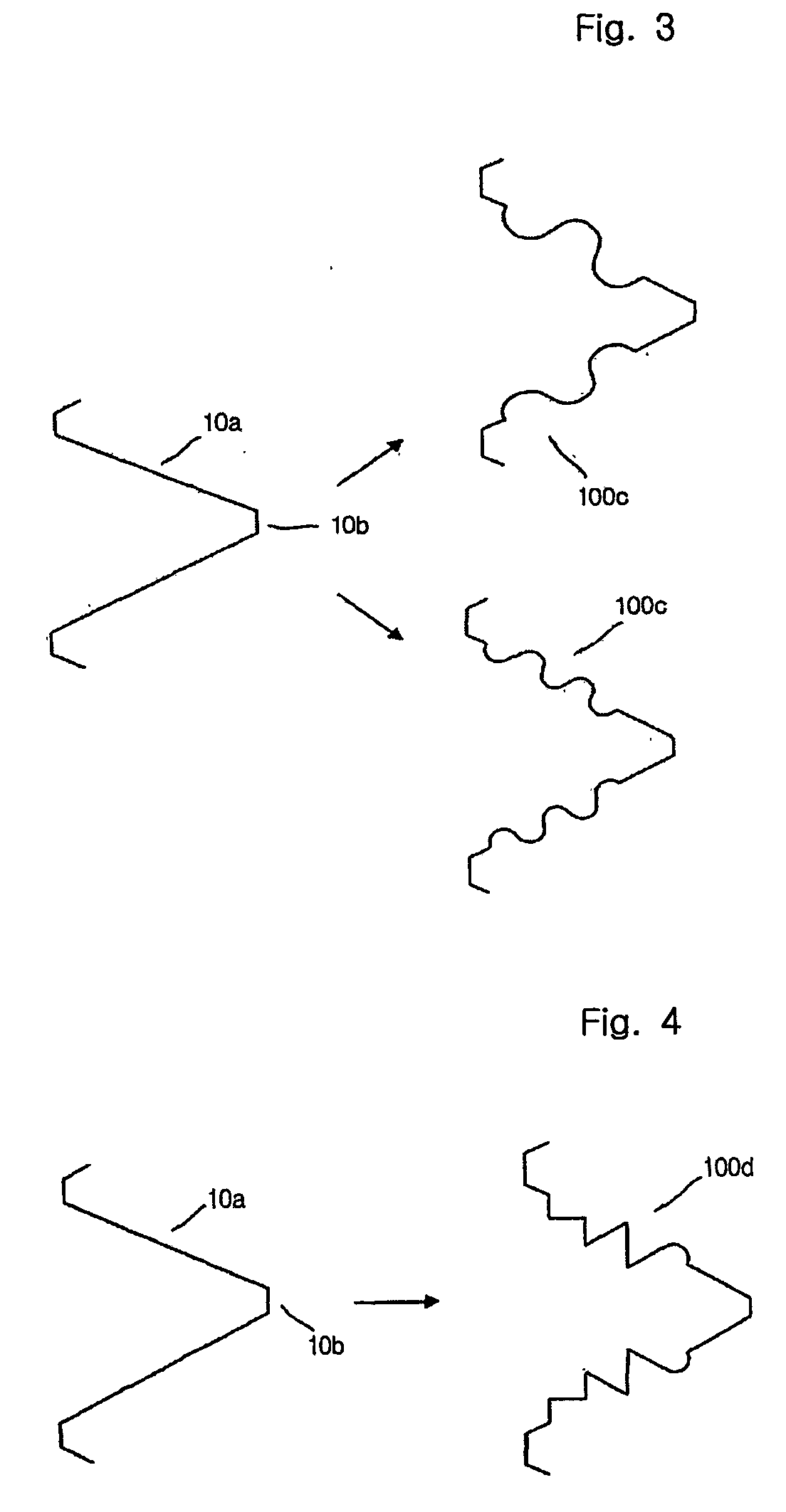
[0027] FIGS. 1 to 3 are a vertical sectional view of triangular, stepped and arcuate patterns formed on the thread inclines of the helical implant according to the present invention, respectively. In this specification, the recesses and the protrusions mentioned above are defined as micro-patterns 100a, 100b, 100...


PUM


Abstract

Disclosed herein is a helical implant. The helical implant is formed with threads theron and each of threads has threads inclines comprising micro-patterns, such as recesses and protrution, on the thread inclines. The micro-patterns on the helical implant may have triangular patterns 100a, stepped patterns 100b and acruate 100c or combination patterns 100d composed of plurality of patterns. The micro-patterns preferably have a cross sectional area of 150 μm. The helical implant has an increased contact area at the fixed portion, so that the volume of the bone induced between the threads 10b is increased from the several dozens of μm level to fifty times that at maximum, thereby dispersing load at the implanted portion and preventing physical damage near the implanted portion.

Description

BACKGROUND OF THE INVENTION [0001] 1. Field of the Invention [0002] The present invention relates to a helical implant, and more particularly to a helical implant, which is formed with micro-patterns on thread inclines of the helical implant fixed in jaw bone tissue, such as the upper jawbone or the lower jawbone, mainly in the field of dentistry. [0003] 2. Description of the Related Art [0004] In general, baby teeth are gradually extracted in sequence of their generation from a predetermined time in order to adapt to growth of the maxillary, and replaced with permanent teeth at their places in the mouth. However, in case of the permanent teeth, once one of the permanent teeth is extracted, it does not regrow. Thus, there has been developed a dental operation for providing a substitution when the permanent tooth is extracted due to decay thereof or an accident. As for the dental operation, when there is a tooth near the extracted tooth, a bridge operation, which grinds the tooth nea...

Claims


Application Information

Patent Timeline
IPC IPC(8): A61C8/00A61C13/00
CPCA61C8/0022A61C8/00A61C13/00
Inventor SUL, YOUNG-TAEK
Owner SUL YOUNG TAEK
Learn More