
Tensioning anchor suitable for blind-hole tendon anchoring and tendon repair

a technology of tendon anchoring and tensioning anchors, which is applied in the direction of building reinforcements, construction, building material handling, etc., can solve the problems of preventing the erection of just described cables, affecting the construction of pillars, and unable to meet the requirements of the construction process

Inactive Publication Date: 2006-09-14
HAYES SPECIALTY MACHINING
View PDF18 Cites 26 Cited by
  • Summary
  • Abstract
  • Description
  • Claims
  • Application Information

AI Technical Summary

Problems solved by technology

The just described cable erection procedure has long proven to be difficult to conduct and far from satisfactory.
For example, the construction of the pillar itself is impeded by having to provide it with the tube and countersink at the time it is formed.
The foregoing barrier construction technique has proven impracticable for use where one side of the concrete pillar is not accessible.
Frequently, one side of such wall is inaccessible, and thus the tendon must be anchored in a blind hole.
It has been observed in actual use that the anchor device in the Hoekstra '499 patent is subject to the threaded rod binding in the anchor body such that free rotation of the threaded rod with respect to the anchor body is not possible.
Intermediate anchorage systems are used in particular whenever the concrete structure is so long that it is cast in sections, or frictional losses would be so great that having a tendon extend from a single live end anchor to a single dead end anchor is inadequate.
A problem that can affect intermediate anchorage systems is the inability to effectively prevent liquid intrusion into the unsheathed portion of the tendon.
However, it is a considerable burden to attempt to slide such a tubular member along the entire length of the tendon so as to form the liquid-tight seal at the intermediate anchorage.
Extensive practice with this technique has shown that it is generally ineffective for preventing liquid intrusion into the interior of the tendon or into the interior of the intermediate anchorage.
A problem inherent in such continuous tendon intermediate anchorage systems is the difficulty of installation.
Often during this “threading” of the anchor onto the tendon, nicks and damage can occur to the sheathing on the tendon.
Often, components of the intermediate anchorage system are omitted or the installation is carried out in an ineffective manner because of the large amount of manual manipulation that is required for the installation of the system.
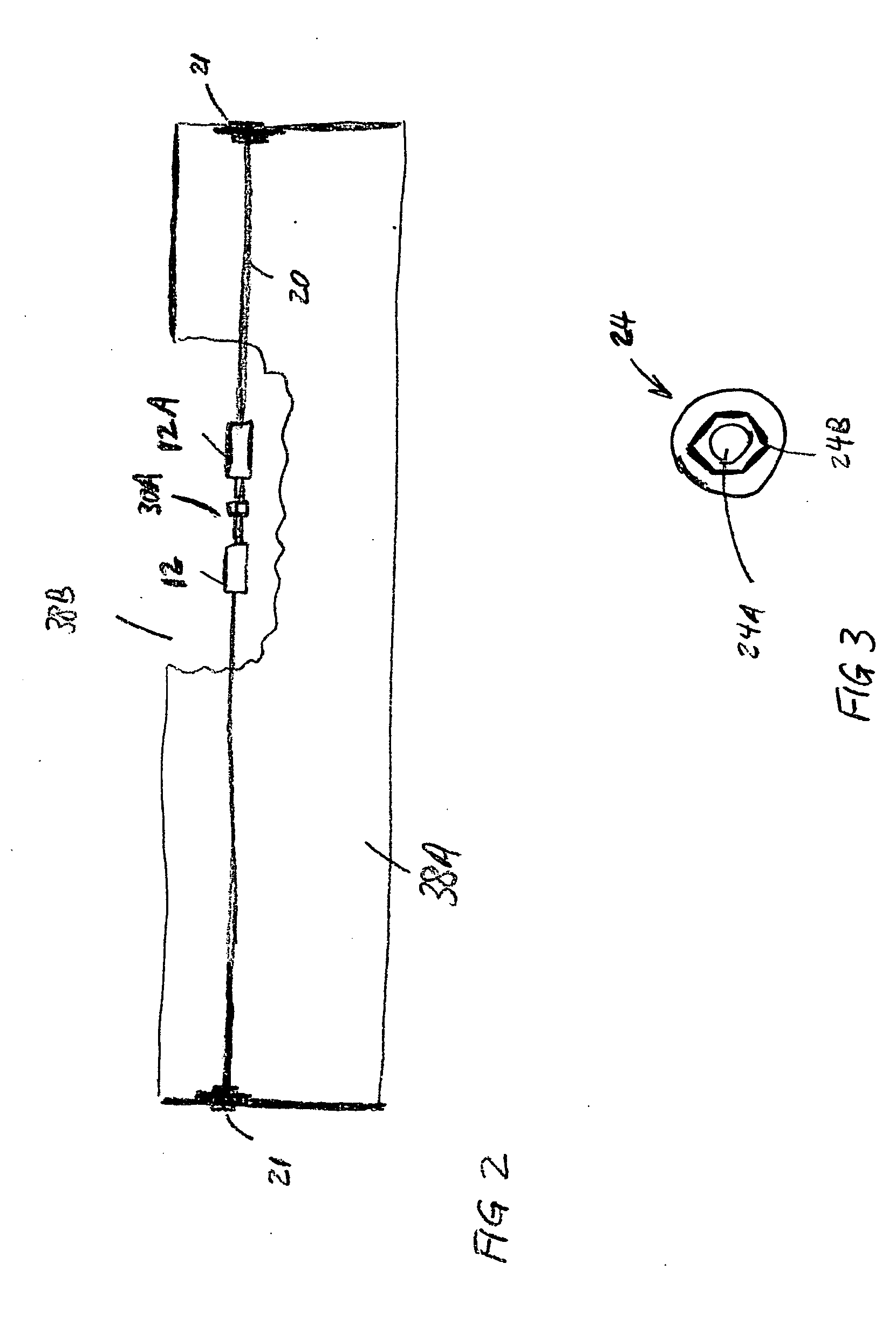
Tendon repair may be made necessary due to localized corrosion effects or mechanical damage to a section of tendon, and where it is impractical to replace an entire tendon.
It is frequently the case that the live end of the tendon is not accessible, or such access is impractical.

Method used


Image

  • Tensioning anchor suitable for blind-hole tendon anchoring and tendon repair
  • Tensioning anchor suitable for blind-hole tendon anchoring and tendon repair
  • Tensioning anchor suitable for blind-hole tendon anchoring and tendon repair

Examples


Embodiment Construction

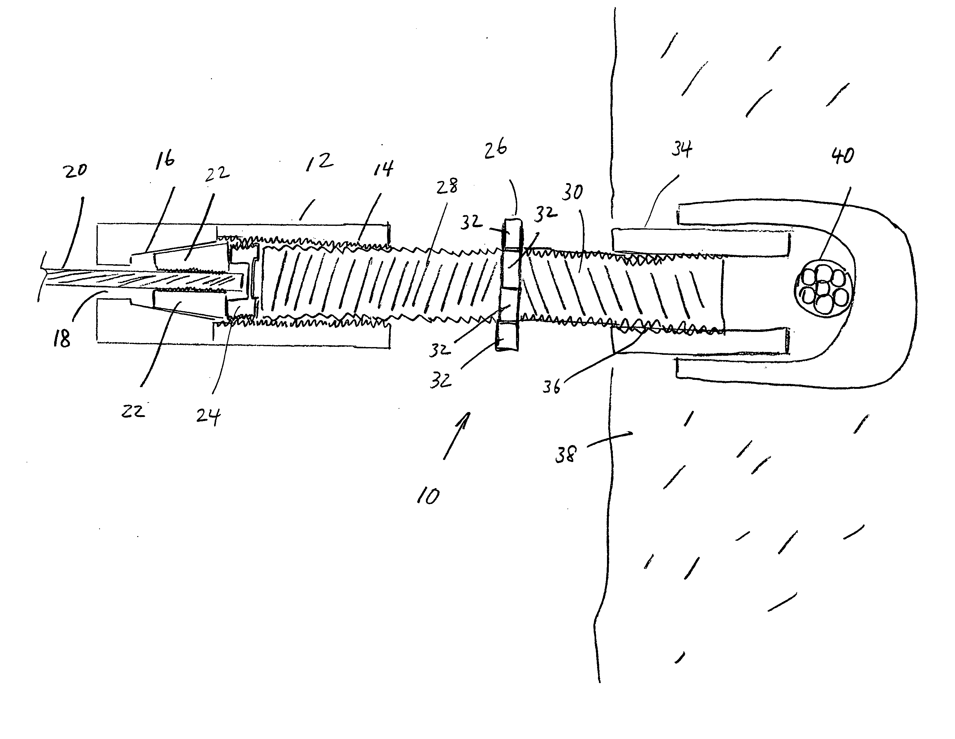
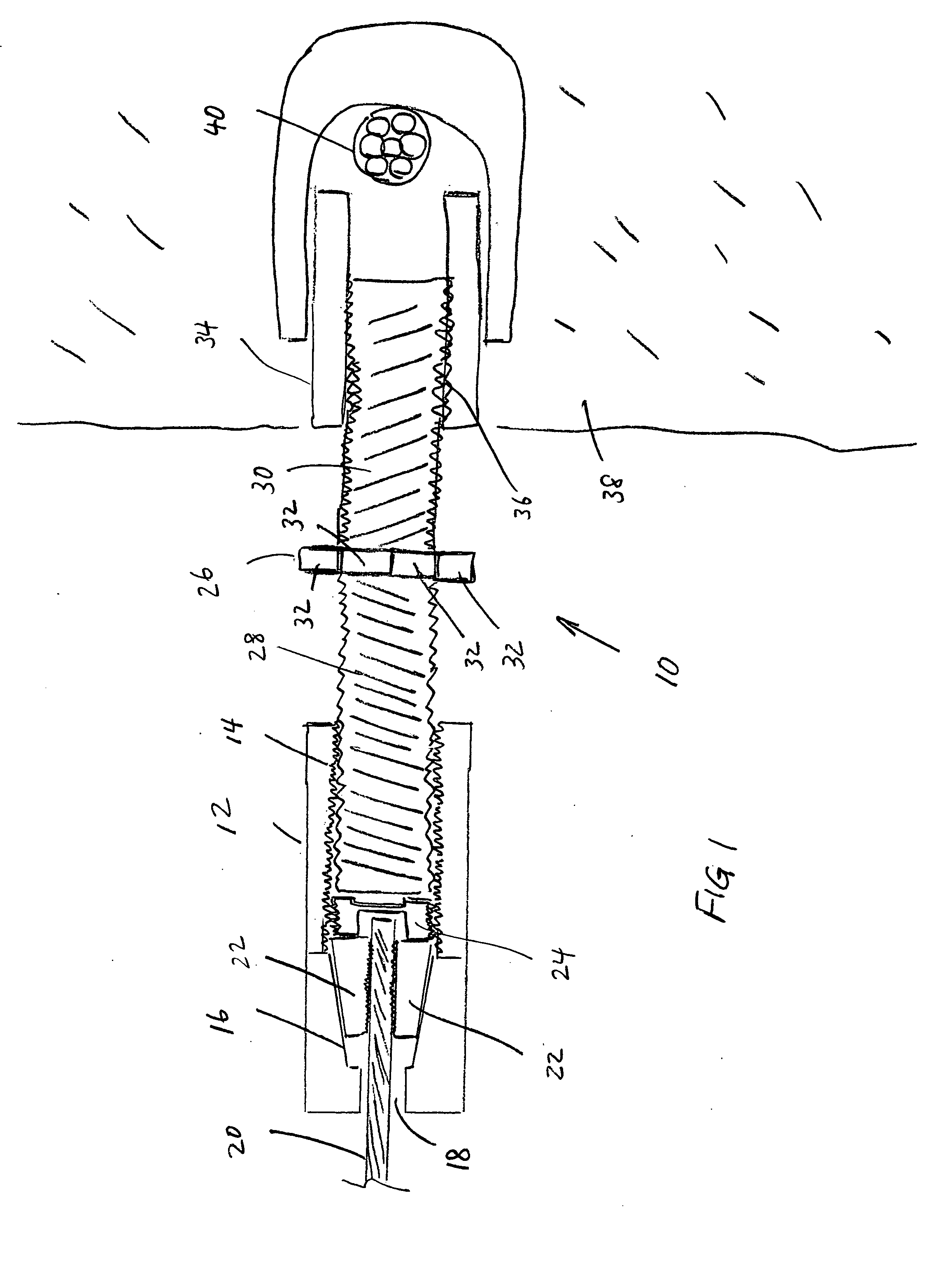
[0025]FIG. 1 shows one embodiment of a tendon anchor system 10 that can be used to anchor a tendon 20 within a blind opening in an anchoring structure, that is, where an opposite side of the anchoring structure is inaccessible. The tendon 20 is typically made from steel or other high strength material. The tendon anchor system 10 includes an anchor body 12, which may be formed from steel or other high strength material.

[0026] The anchor body 12 includes a device to retain the tendon 20 within, such that under tension, the tendon 20 is restrained from longitudinal movement out of the anchor body 12. The device in the present embodiment can include a generally tapered wedge receiving bore 16, and a wedge 22 adapted to be applied to the exterior of the tendon 16 and to fit within the receiving bore 16. The wedge 22 may include a threaded interior surface or similar arrangement of gripping elements to grip the outer surface of the tendon 20, and may be formed from a plurality of wedge ...


PUM


Abstract

A tendon anchor system includes an anchor body adapted to receive a tendon through one end. The anchor body has a threaded coupling at the other end. A retaining device is disposed within the anchor body for retaining the tendon within the anchor body. An anchor is disposed within an anchoring structure. The anchor has a threaded coupling. The threaded coupling in the anchor has an opposite thread direction to the threaded coupling in the anchor body. A jack screw threadedly engages with both the threaded coupling in the anchor body and in the anchor.

Description

CROSS-REFERENCE TO RELATED APPLICATIONS [0001] Not applicable. STATEMENT REGARDING FEDERALLY SPONSORED RESEARCH OR DEVELOPMENT [0002] Not applicable. BACKGROUND OF INVENTION [0003] 1. Field of the Invention [0004] The invention relates generally to the field of concrete reinforcing systems. More particularly, the invention relates to devices used to anchor a reinforcing tendon in a blind hole in a concrete structure, and also relates to devices used to repair or extend reinforcing tendons. [0005] 2. Background Art [0006] Concrete construction techniques frequently make use of cables or tendons for various purposes, including forming barriers and for structural concrete reinforcement such as prestressing and post tensioning. [0007] Cable barriers, such as those used for pedestrian safety lines disposed beside parking garage ramps and parking garage vehicle barriers, are commonly built so that tendons or cables traverse a span between building structures such as concrete pillars. Span...

Claims


Application Information

Patent Timeline
IPC IPC(8): E04C5/08
CPCE04C5/12E04C5/165E04G21/12E04G23/0218
Inventor HAYES, NORRIS O.DRAGINIS, RANDYAGAN, RICHARD K.
Owner HAYES SPECIALTY MACHINING
Learn More