
Channel equalizer and method of equalizing a channel

a channel equalizer and channel equalization technology, applied in the field of channel equalizer and channel equalization method, can solve the problems of complex modulation and demodulation system used to modulate and demodulate signals, interference between symbols in signals, short between signals,

Inactive Publication Date: 2006-09-07
SAMSUNG ELECTRONICS CO LTD
View PDF6 Cites 12 Cited by
  • Summary
  • Abstract
  • Description
  • Claims
  • Application Information

AI Technical Summary

Benefits of technology

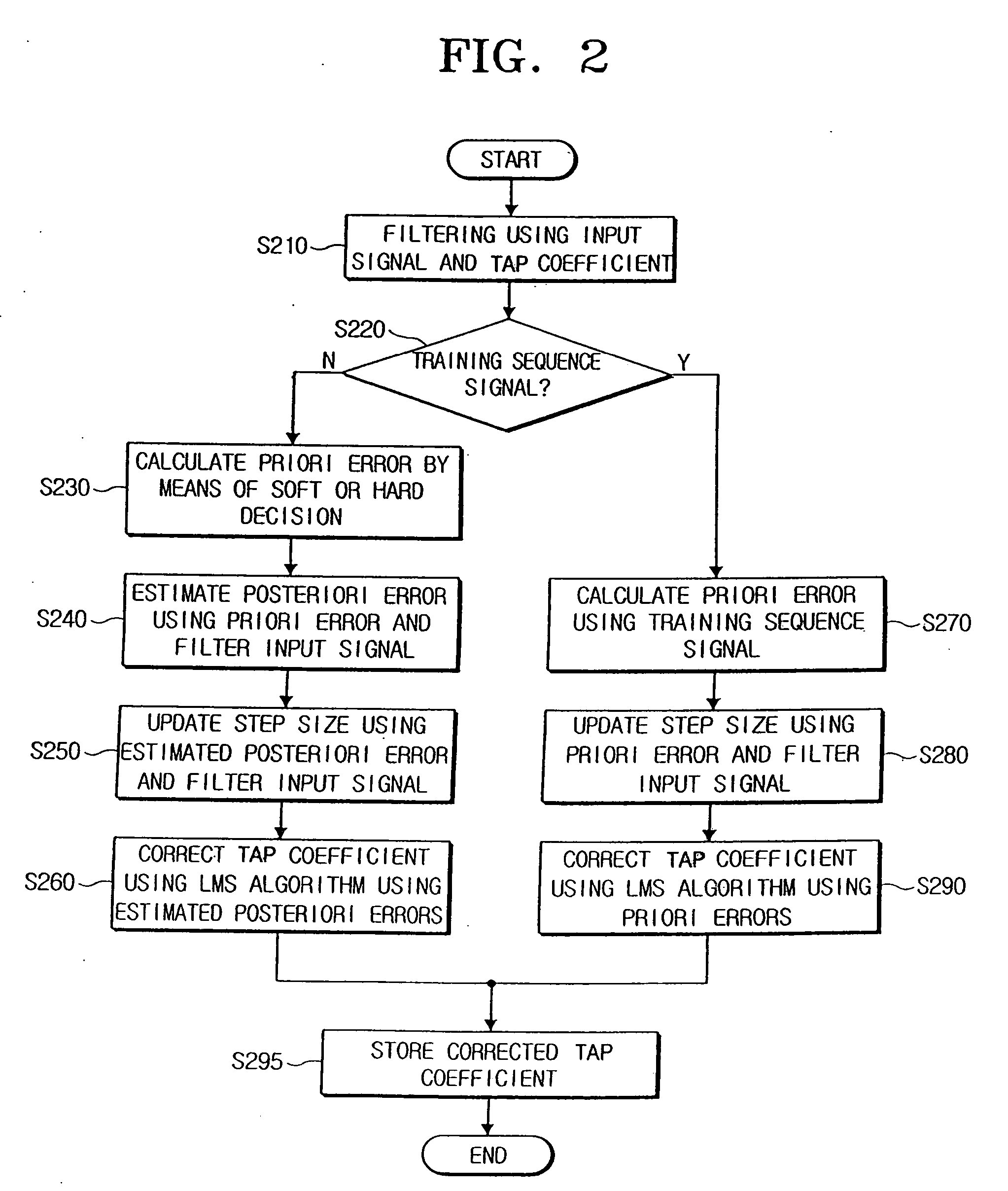
[0011] The present general inventive concept provides a channel equalizer and a method of equalizing a channel which can equalize the channel by adaptively removing interference between symbols occurring between the channels using a priori error and an estimated posteriori error.
[0017] The first correction unit may correct the second adaptive step size algorithm using the generated estimated posteriori error signal, the signal input to the filter unit, and the adaptive step size.

Problems solved by technology

However, a distance between signals is short causing interference to occur between symbols in the signals.
Thus, a modulation and demodulation system used to modulate and demodulate the signals becomes more complex.
In particular, a multi path has a substantial amount of interference between the symbols of the signals due to a phase change and a time delay of the transmitted signal, so that the substantial amount of interference causes bit detection errors at the receiving end.
However, both techniques (i.e., the channel equalization method and the adaptive channel equalization method) described above, have a low convergence rate when low MSEs are produced, and high MSEs when a high convergence rate is produced, so that the two conditions (i.e., high convergence rate and a low MSE) can not be satisfied at the same time.

Method used


Image

  • Channel equalizer and method of equalizing a channel
  • Channel equalizer and method of equalizing a channel
  • Channel equalizer and method of equalizing a channel

Examples


Embodiment Construction

[0036] Reference will now be made in detail to the embodiments of the present general inventive concept, examples of which are illustrated in the accompanying drawings, wherein like reference numerals refer to the like elements throughout. The embodiments are described below in order to explain the present general inventive concept by referring to the figures.

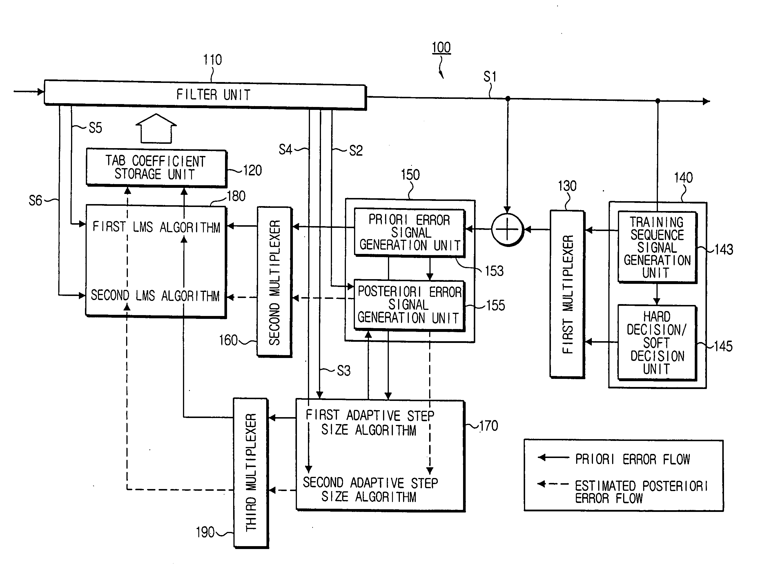
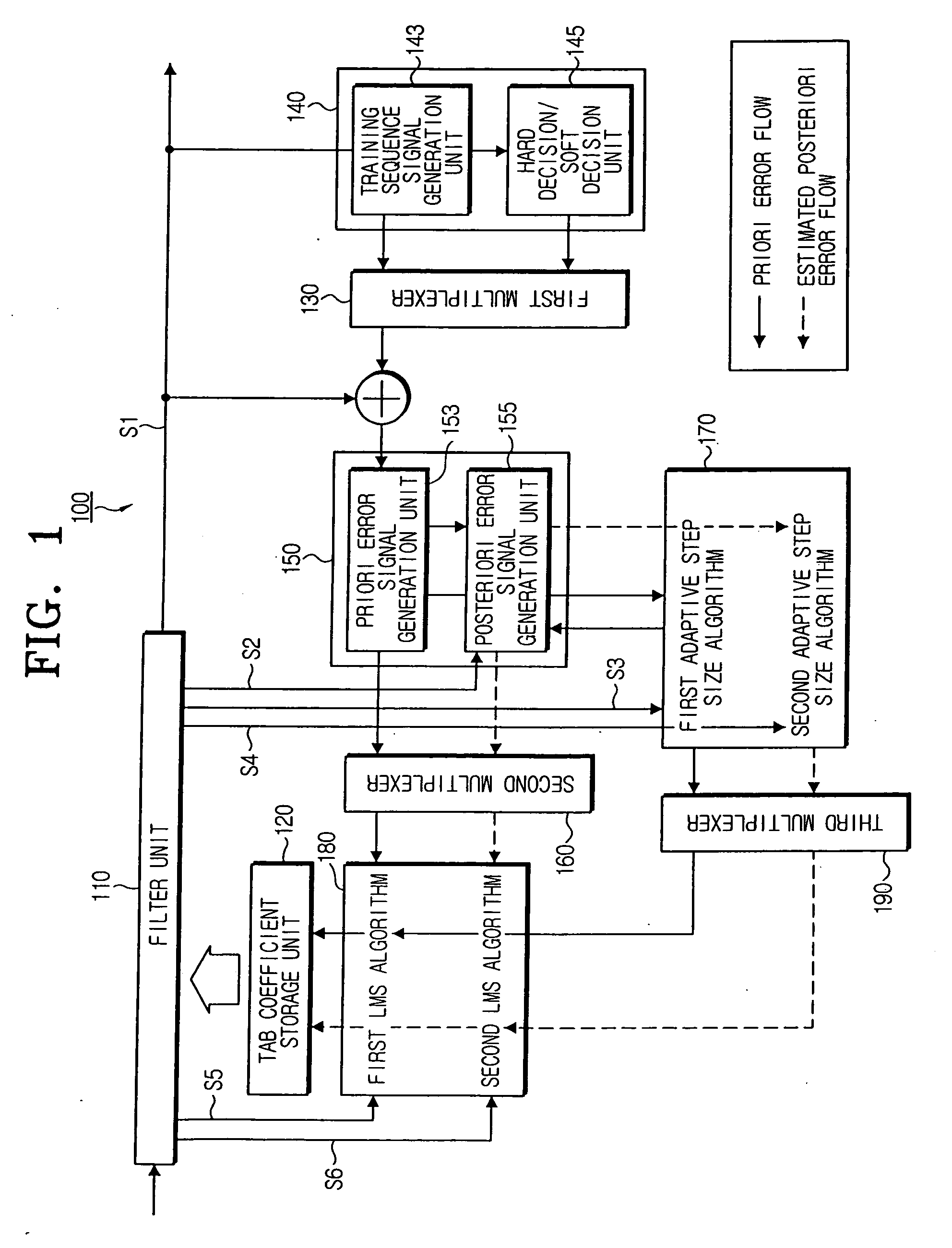
[0037]FIG. 1 is a block diagram illustrating a channel equalizer 100 in accordance with an embodiment of the present general inventive concept.

[0038] Referring to FIG. 1, the channel equalizer 100 includes a filter unit 110, a first multiplexer 130, a decision unit 140, an error signal generation unit 150, a first correction unit 170, a second multiplexer 160, a second correction unit 180, and a third multiplexer 190.

[0039] The filter unit 110 has a Tapped Delayed Line structure, and filters an input training sequence signal and an input data signal in response to tap coefficients stored in a tap coefficient storage unit 120...


PUM


Abstract

A channel equalizer and a method of equalizing a channel. The channel equalizer includes a filter unit to filter an input training sequence signal and an input data signal according to a tap coefficient, a first multiplexer to calculate a priori error of each of the training sequence signal and the data signal, a decision unit to generate the training sequence signal and to soft-determine or hard-determine an output signal of the filter unit, an error signal generation unit to generate a priori error signal using an output signal of the decision unit and to generate an estimated posteriori error signal using the priori error signal, a first correction unit to correct a first adaptive step size algorithm using the signal input to the filter unit and the generated priori error signal and to correct a second adaptive step size algorithm using the signal input to the filter unit and the estimated posteriori error signal, and a second multiplexer to select one of the corrected first adaptive step size algorithm and the corrected second adaptive step size algorithm to be applied to the training sequence signal and the data signal, respectively.

Description

CROSS-REFERENCE TO RELATED APPLICATIONS [0001] This application claims the benefit of Korean Patent Application No. 2005-18114, filed on Mar. 4, 2005 in the Korean Intellectual Property Office, the disclosure of which is incorporated herein by reference in its entirety. BACKGROUND OF THE INVENTION [0002] 1. Field of the Invention [0003] The present general inventive concept relates to a channel equalizer and a method of equalizing a channel, and in particular, to a channel equalizer and a method of equalizing a channel by adaptively removing interference between symbols. [0004] 2. Description of the Related Art [0005] A digital TV can receive an original signal without any distortion resulting from noise in transit, because video and audio signals are converted to digital signals and are then transmitted to a receiver, unlike in an analog TV. Additionally, a digital transmission can also transmit more data on a transmission channel having the same band as compared to an analog trans...

Claims


Application Information

Patent Timeline
Patent Type & Authority Applications(United States)
IPC IPC(8): G06F7/38
CPCH04L25/03019H04L2025/03611H04L2025/03687H04L2025/03726H04N5/211H04N5/4401H04N21/426D04B39/04
Inventor PARK, SUNG-WOOSEO, JONG-SOOJEONG, HAE-JOOBAEK, JONG-SEOB
Owner SAMSUNG ELECTRONICS CO LTD
Learn More