
Surface mount electrical resistor with thermally conductive, electrically insulative filler and method for using same

a technology of electrical resistor and filler, which is applied in the manufacture of resistor chips, resistor details, resistor manufacturing, etc., can solve the problems of limited size or thermal efficiency, preventing any significant improvement in heat dissipation, and not necessarily reducing the power requirements of the system, so as to enhance the ability of the filler to conduct hea

Active Publication Date: 2006-09-07
VISHAY DALE ELECTRONICS INC
View PDF12 Cites 16 Cited by
  • Summary
  • Abstract
  • Description
  • Claims
  • Application Information

AI Technical Summary

Benefits of technology

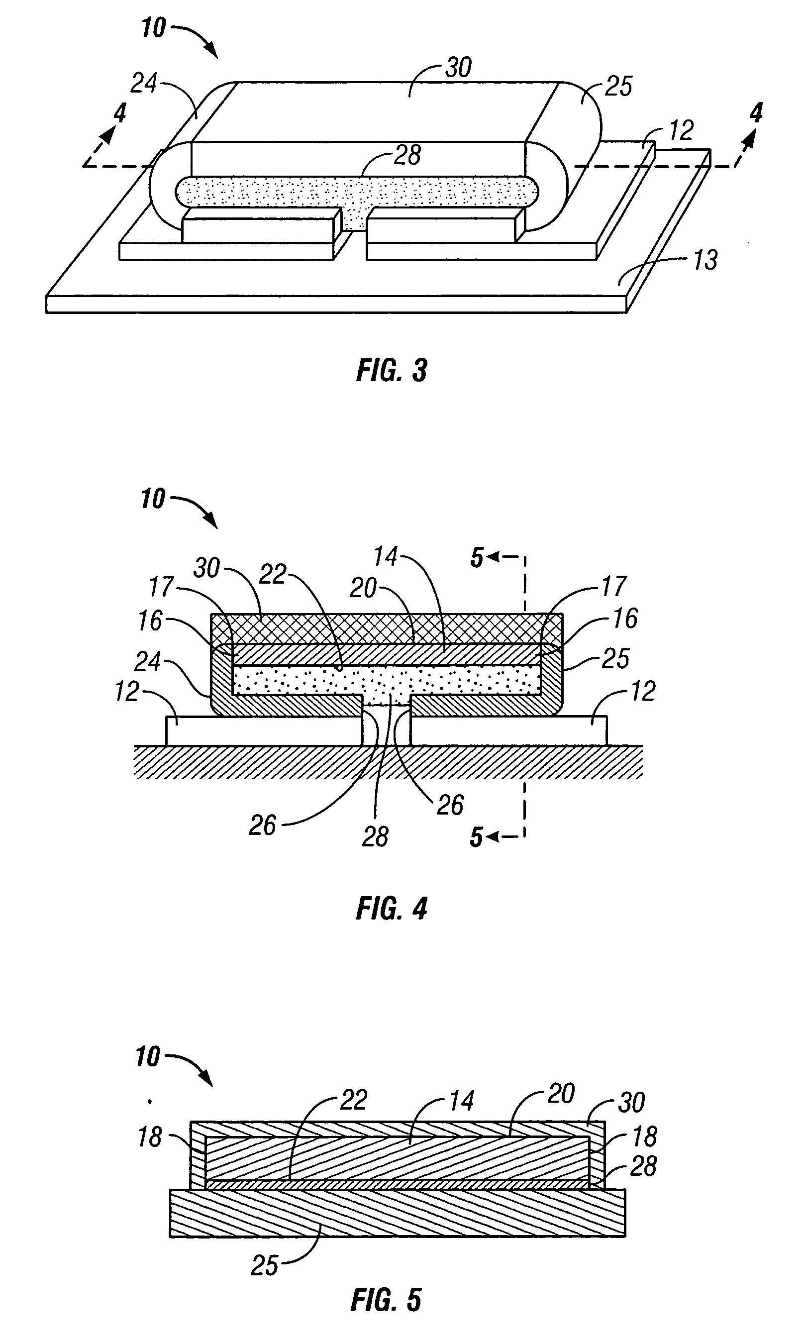
[0024] According to another feature of the present invention, the filler is bonded to both the lower surface of the resistance element and the first and second terminations so as to enhance the ability of the filler to conduct heat from the resistance element to the first and second terminations.

Problems solved by technology

However, the power requirements of the system are not necessarily reduced in magnitude as the electronic systems and their components get physically smaller.
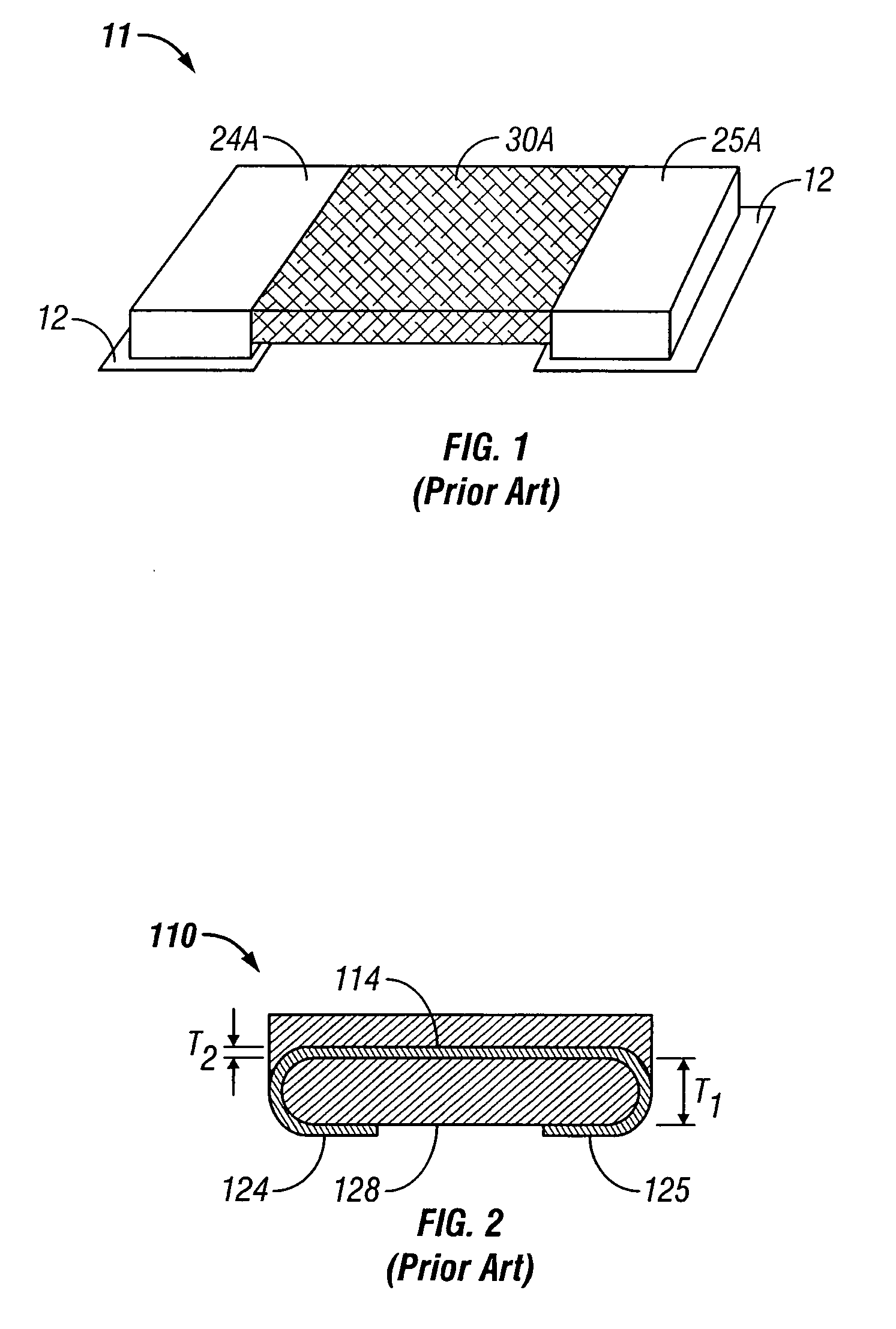
Other prior art resistors have terminations that are long and wrapped underneath the resistive element, but are not optimized for thermal conductivity from the resistive elements, thereby precluding any significant improvement in heat dissipation.
Still other prior art terminations for heat dissipation are not used for electrical connection to the circuit assembly.
However, all of these prior art terminations have limited size or thermal efficiency and therefore limited capacity for heat dissipation.

Method used


Image

  • Surface mount electrical resistor with thermally conductive, electrically insulative filler and method for using same
  • Surface mount electrical resistor with thermally conductive, electrically insulative filler and method for using same
  • Surface mount electrical resistor with thermally conductive, electrically insulative filler and method for using same

Examples


Embodiment Construction

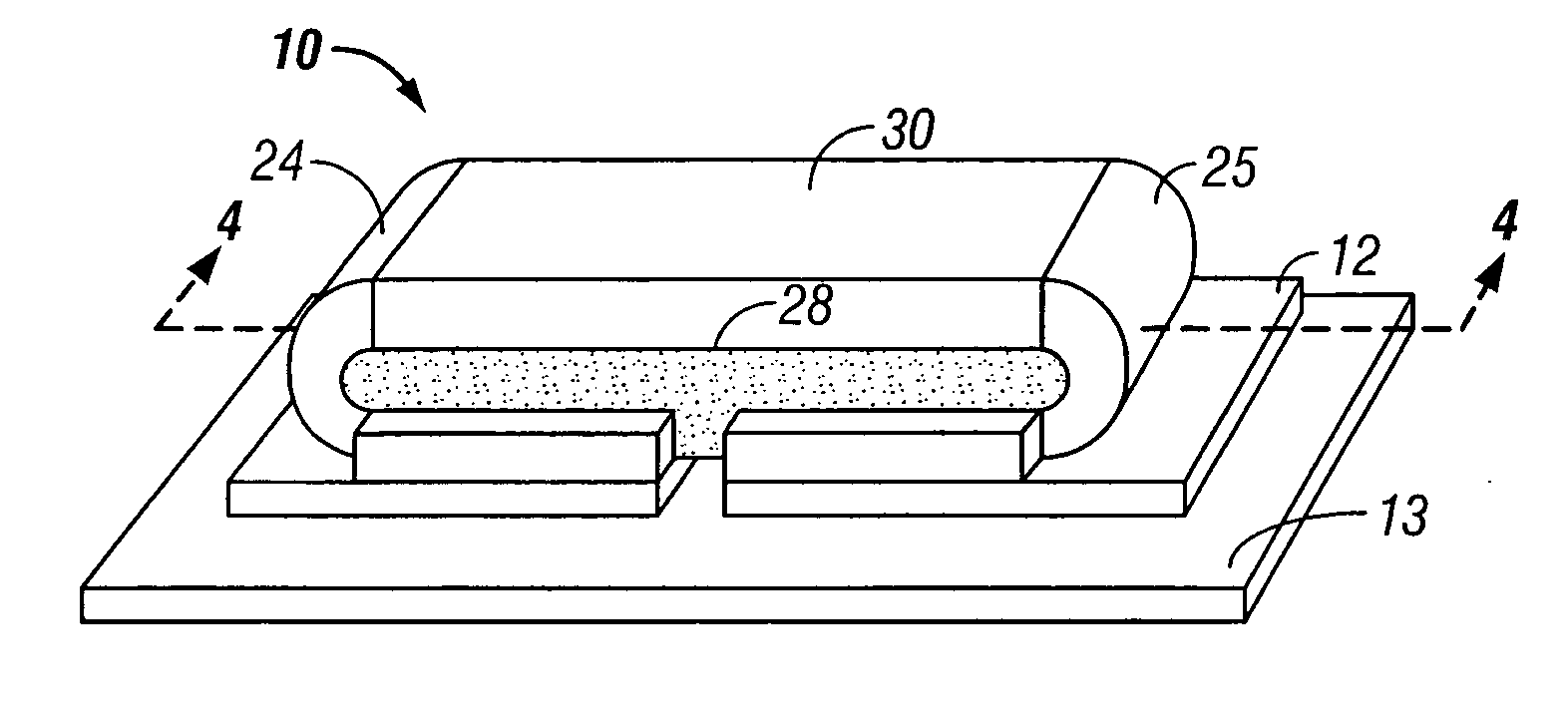
[0036] The resistor of the present invention is generally designated in the drawings by the reference numeral 10. The resistor 10 is a surface-mount resistor adapted to be mounted on an electrical circuit assembly, such as pads 12 on circuit board 13. The resistor 10 includes a resistive element 14 having opposite ends 16, opposite sides 18, a top surface 20 and a bottom surface 22. The resistor 10 also includes terminals or terminations 24 and 25 extending from the opposite ends 16 of the resistive element 14. The terminations 24, 25 are welded to the ends of resistance element 14 along weld lines 17. The terminations 24 and 25 are elongated and folded to a position beneath the resistive element 14, as seen in FIGS. 3 and 4. The outer ends 26 of the terminations are closely spaced with a small gap there between. The distance between the outer ends 26 is in the range of 0.0254 mm (2 mil) to one-third of the length of resistor 10. Normally this is about 0.5 ml (20 mils).

[0037] A the...


PUM


Abstract

An electrical resistor is provided with a resistive element and terminations extending from opposite ends of the resistive element. The terminations are folded under the resistive element, with a thermally conductive and electrically insulative filler being sandwiched and bonded between the resistive element and the terminations. The terminations provide for mounting of the resistor to an electronic circuit assembly. The intimate bond between the resistive element, filler and terminations allow for enhanced dissipation of heat generated in the use of the resistive element, so as to produce a resistor which operates at a lower temperature, and improves component reliability.

Description

BACKGROUND OF THE INVENTION [0001] This invention relates to a surface mount electrical resistor with thermally conductive, electrically non-conductive filler and method for using same. [0002] Electronic systems such as cell phones, computers, consumer electronics and the like continue to get smaller and smaller. As the systems shrink in size, smaller electronic components are required. However, the power requirements of the system are not necessarily reduced in magnitude as the electronic systems and their components get physically smaller. Therefore, the heat generated by the components must be managed so as to maintain safe and reliable operating temperatures for the systems. [0003] Resistors are a primary component in the electronic circuit assemblies of these various systems. Prior art resistors have many different designs. Some prior art resistors have terminations that are very short, in comparison to the length of the resistive element, and extend outwardly from the ends of ...

Claims


Application Information

Patent Timeline
IPC IPC(8): H01C1/012
CPCH01C1/084H01C1/144H01C1/148H01C17/006H01C1/14H01C17/00
Inventor SMITH, CLARK L.VEIK, THOMAS L.WYATT, TODD L.BERTSCH, THOMAS L.BRUNE, RODNEYMAC ARTHUR, WILLIAM
Owner VISHAY DALE ELECTRONICS INC
Learn More