
Extended matching range tuner

a tuner and shunt technology, applied in the field of antenna tuning, can solve the problems of limiting the lowest load impedance that can be matched, not effectively in the circuit, and almost fully disengage the capacitor, so as to achieve exceptional matching, reduce the capacitance of the input matching capacitor, and increase the shunt capacitance to ground

Inactive Publication Date: 2006-09-07
JUE MARTIN F
View PDF2 Cites 8 Cited by
  • Summary
  • Abstract
  • Description
  • Claims
  • Application Information

AI Technical Summary

Benefits of technology

[0025] Rather than using a high-voltage fixed shunt capacitor between the input to the tuner and ground for a T network tuner, in the subject invention one uses a variable air gap capacitor that is ganged to the input matching capacitor. The salient feature of the subject invention is that as one decreases the capacitance of the input matching capacitor, one increases the shunt capacitance to ground. This results in an extremely broadbanded tuner that can work from 160 meters to 10 meters and provide exceptional matching regardless of antenna impedance.
[0028] Thus, for the higher frequencies, when the minimum capacitance of the variable input matching capacitor is not low enough, one is able to further lower this minimum capacitance problem by using a variable shunt capacitor that increases its capacitance as one decreases the capacitance of the input matching capacitor. On the other hand, at the higher frequencies when the load impedance is lower, unless one can remove the shunt capacitance the maximum effective input matching capacitance will be limited which limits the lowest load impedance that can be matched. However, since the shunt capacitance goes down when the input matching capacitance goes up to take care of the lower impedance, it will not impede the input matching capacitor and it can perform its matching function.
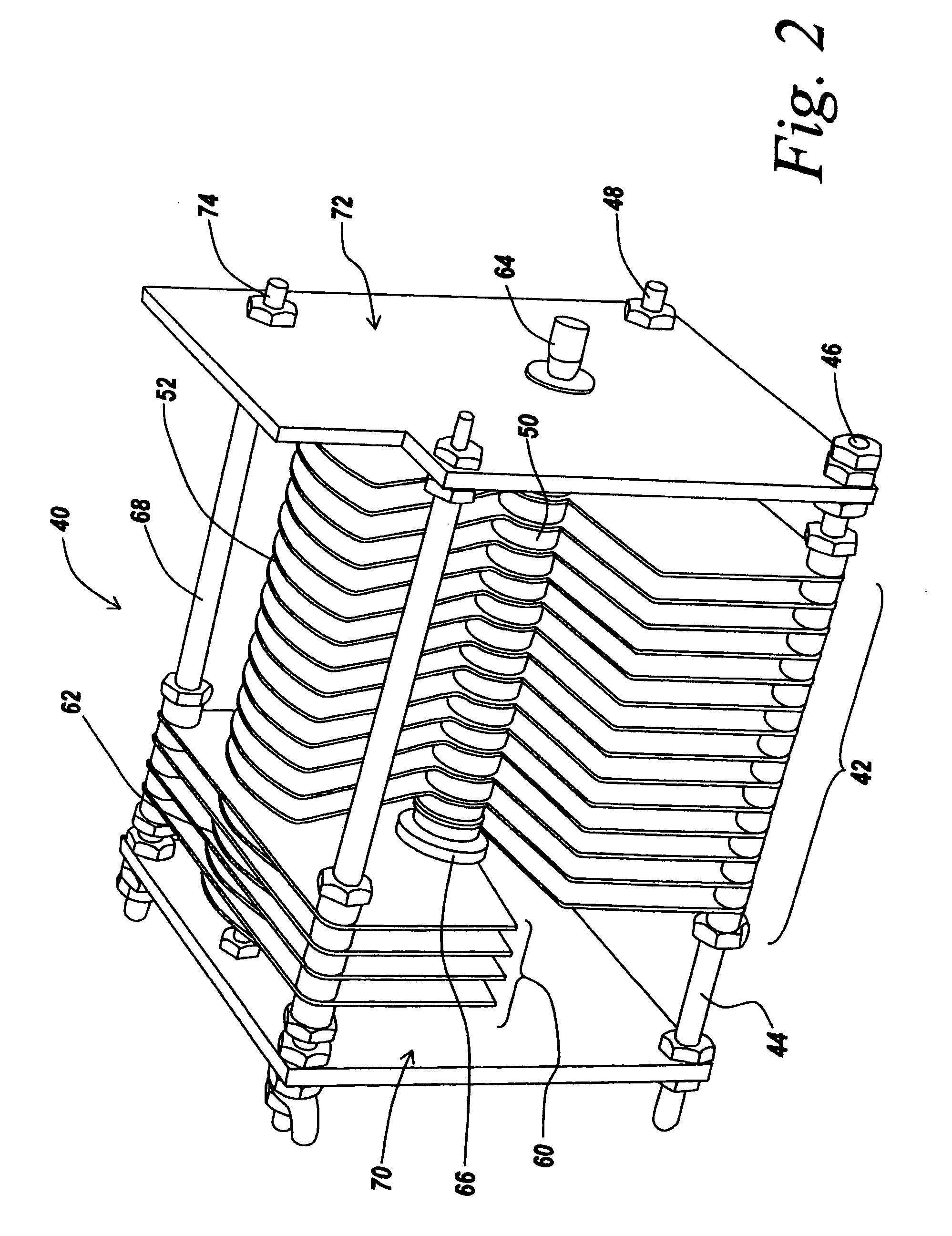
[0029] In one embodiment, this ganged capacitance arrangement is provided by a simple variable capacitor assembly in which, for the larger input matching capacitor, one has a large number of primary stator plates that interact with the rotor plates as the rotor plates are rotated into the stators. However, one provides the assembly with a reduced number of secondary stator plates rotated 180 degrees away from the position of the primary stator plates, with rotor plates for the secondary capacitor attached to the same shaft and aligned with the primary rotor plates.
[0030] The result is that, as one rotates the rotor plates into the primary stators, one simultaneously rotates the rotor plates out of the secondary capacitor stators and vice versa. What this means is that, as one reduces the engagement of the rotor plates of the primary variable capacitor, one increases the engagement of the rotor plates associated with the secondary capacitor stator plates. Thus in the tuner, what one does is to increase the shunt capacitance while reducing the capacitance of the input matching capacitor.

Problems solved by technology

On the other hand, at 160 meters, when the input matching capacitor is almost fully engaged, the shunt capacitor is almost fully disengaged so that it is not effectively in the circuit.
On the other hand, at the higher frequencies when the load impedance is lower, unless one can remove the shunt capacitance the maximum effective input matching capacitance will be limited which limits the lowest load impedance that can be matched.

Method used


Image

  • Extended matching range tuner
  • Extended matching range tuner
  • Extended matching range tuner

Examples


Embodiment Construction

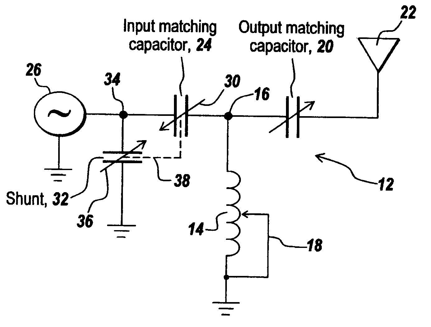
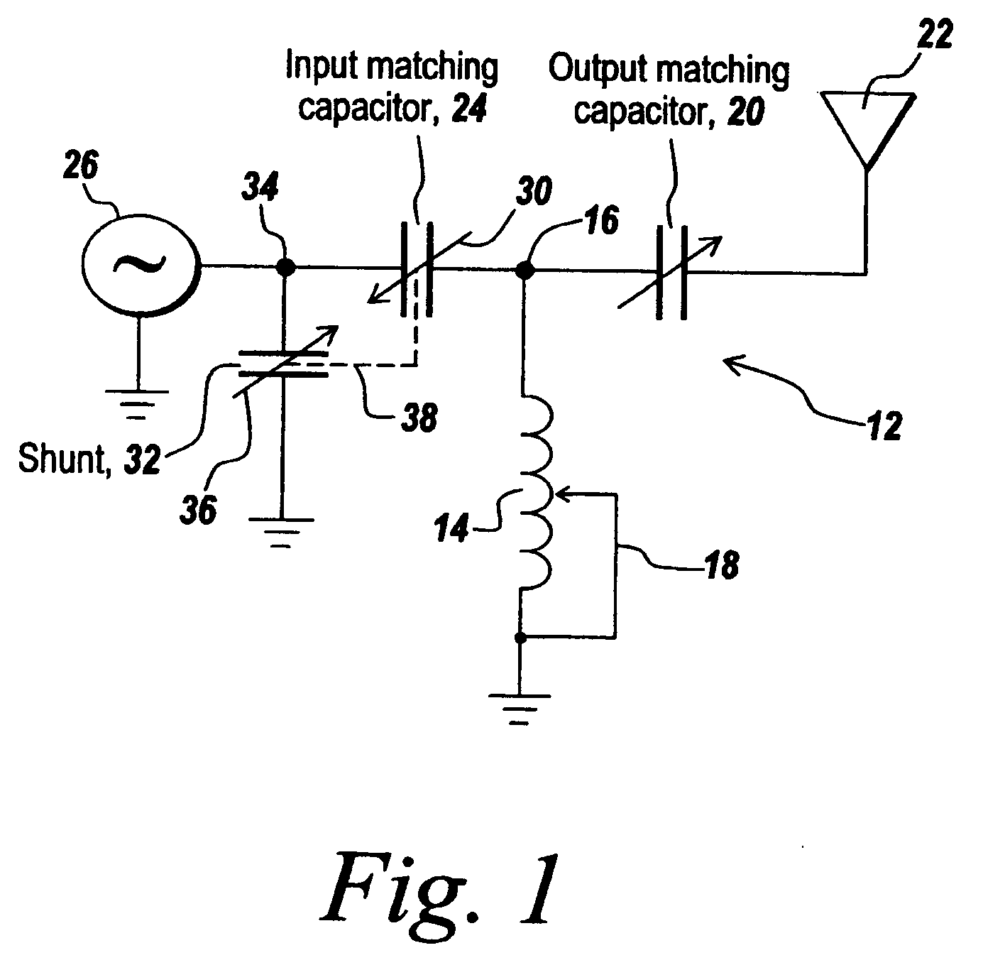
[0044] Referring now to FIG. 1, a T network antenna tuner 12 has a tapped or variable inductor 14 connected between ground and a point 16. Inductor 14 is provided with a tap 18 so that the inductance can be readily varied.

[0045] A variable output matching capacitor 20 is coupled between point 16 and antenna 22, whereas a variable input matching capacitor 24 is connected between point 16 and a signal source 26. Signal source 26 is typically a transmitter having an output impedance of 50 ohms. Capacitor 24 has an arrow 30 going down through it and pointing downwardly to the left, whereas a shunt capacitor 32 connected between signal source input 34 and ground has an arrow 36 pointed in a direction opposite to arrow 30. As can be seen by dotted line 38, the two capacitors, namely capacitor 24 and capacitor 32, are ganged together or arranged such that decreasing the capacitance of capacitor 24 results in increasing the capacitance of capacitor 32. The increased shunt capacitance assis...


PUM


Abstract

In a T network tuner, a variable shunt capacitor is provided between the signal input and ground that is ganged to the variable input matching capacitor. The operation is mechanically arranged such that, as one decreases the capacitance of the variable input matching capacitor, one increases the capacitance of the shunt capacitor to assist in high frequency matching, both to increase the maximum matchable load resistance and to decrease the minimum matchable load resistance. The variable shunt capacitor therefore assists at the high frequency ranges to bring the antenna impedances down to the transmitter output impedance, thus to establish an extended matching range tuner capable working between 160 and 10 meters.

Description

FIELD OF THE INVENTION [0001] This invention relates to antenna tuning and more particularly to the use of a variable shunt capacitor coupled to the input matching capacitor in a T network such that when the variable input matching capacitor is tuned to reduce its capacitance, the capacitance of the shunt capacitor is increased. BACKGROUND OF THE INVENTION [0002] As is well known, tuners between a transmitter and an antenna are used to match the antenna impedance to the impedance at the output of a transmitter. In amateur radio service, for instance, one is seeking to match antennas to transmitters in various bands, for instance, from 160 meters through 10 meters. When using a T network, while a variable input matching capacitor can be utilized for matching an antenna to the 50-ohm output of a transmitter at the low frequency bands, when trying to use the same circuit to tune 10-meter antennas, even when the variable input matching capacitor is completely open, there is nonetheless ...

Claims


Application Information

Patent Timeline
IPC IPC(8): H03H7/38
CPCH03H7/40
Inventor JUE, MARTIN F.
Owner JUE MARTIN F
Learn More