Shoulder implant for glenoid replacement and methods of use thereof

Active Publication Date: 2006-08-31
SHOULDER INNOVATIONS
View PDF70 Cites 188 Cited by
  • Summary
  • Abstract
  • Description
  • Claims
  • Application Information

AI Technical Summary

Benefits of technology

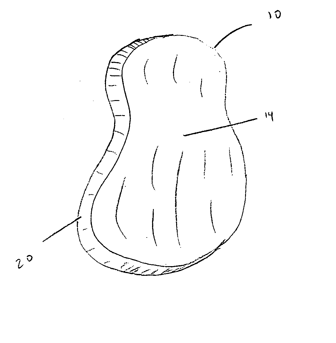
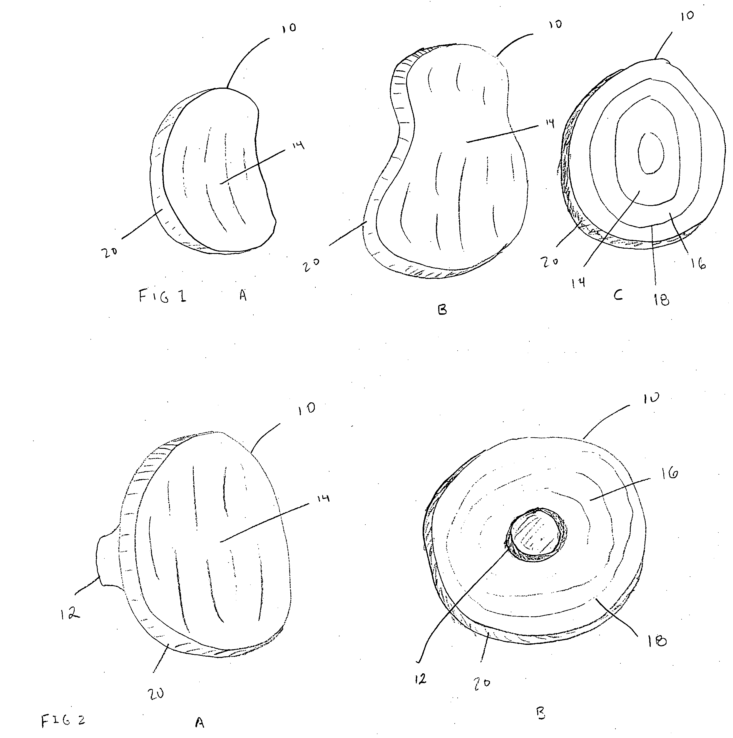
[0007] In one aspect, the invention features an inset glenoid shoulder implant that is implanted within the glenoid vault, thereby allowing circumferential cortical support along the rim of the prosthesis, which improves fixation strength in comparison to current glenoid implants. Another advantage of the glenoid implant is that it requires only a minimal amount of bone removal for implantation.
[0014] In another aspect of the invention, the glenoid implant can be used in patients with deficient glenoid bone due to fracture or severe arthritis. In preferred embodiments, the glenoid implant has none, one, two, or three or more short backside pegs that do not extend beyond about 10 mm outwardly from the backside (medial) surface of the glenoid implant. In a preferred embodiment, the peg or pegs do not extend beyond about 8 mm from the backside (medial) surface of the glenoid implant. Because the glenoid implant lacks a long backside extension, it can be safely placed inside a glenoid vault with minimal depth. This minimizes the risk of fracturing the body of the scapula or injuring the suprascapular nerve or rotator cuff.
[0019] 2—Avoiding an extensive inferior capule incision increases the safety of the procedure by reducing the risk of injury to the axillary nerve.
[0020] 3—Providing an implant that can be placed in the glenoid without extensive, circumferential glenoid exposure would allow general orthopedists to perform a shoulder replacement with less difficulty and potentially fewer complications.

Problems solved by technology

Keeled and pegged glenoid implants suffer from several disadvantages, which limit their lifespan once implanted and reduce the number of indications for which they can be used when the age of the patient is a factor.
For example, the glenoid implants can loosen due to poor fixation within the bone, and they are prone to wear and fatigue failure of the polyethylene due to adhesion, abrasion, and shear stress.
As arthritis progresses, the humeral head can wear medially and destroy the foundation of glenoid bone.
Thus, a typical keel or peg design can broach the glenoid vault and injure the suprascapular nerve along the suprascapular notch or spinoglenoid notch with resultant denervation injury to the rotator cuff muscles.
Broaching through the glenoid vault can also fracture the body of the scapula and cause early implant loosening.
There are also several disadvantages associated with current glenoid replacement surgical techniques.
Since the axillary nerve is located within 1 cm of the inferior capsule, there is potential risk of axillary nerve injury with resultant denervation injury to the deltoid muscle when these releases are performed.
However, use of the current keeled or pegged glenoid implants requires this extensive glenoid exposure for proper fitting and placement.
Current glenoid replacement surgery also requires a long skin incision and extensive soft tissue stripping in order to fully expose the glenoid circumferentially, which produces a cosmetically unappealing scar.
Therefore, many surgeons have difficulty preparing the glenoid site for a total shoulder replacement using the current techniques.
Because there are more than 20,000 shoulder arthoplasty surgeries performed per year, many U.S. patients incur a risk of continued pain and disability, neuromuscular injuries, or failed shoulder prostheses requiring revision surgery.

Method used


Image

  • Shoulder implant for glenoid replacement and methods of use thereof
  • Shoulder implant for glenoid replacement and methods of use thereof
  • Shoulder implant for glenoid replacement and methods of use thereof

Examples


example 1

[0089] A 62 year old woman presented with progressive, debilitating shoulder pain from osteoarthritis, which she had experienced for approximately 15 years. She had constant pain (rated 9 / 10) and difficulty washing her hair, fastening her bra, lifting a cup of coffee, and performing other daily activities. The preoperative radiographs and CT scan showed severe shoulder arthritis and glenoid bone loss that would preclude the use of a keeled or pegged glenoid implant. There was concern that a hemiarthroplasty procedure (replacement of the humeral ball, which would leave the arthritic glenoid socket bare) would not relieve the patient's pain.

[0090] A total shoulder replacement using an inset glenoid implant of the invention and a standard humeral implant was performed. The smaller size and circumferential fixation of the inset glenoid implant allowed safe placement of the prosthesis within the confines of the patient's deficient glenoid cavity.

[0091] The deficient glenoid vault was n...

example 2

[0093] An 81 year old woman presented with severe shoulder pain and stiffness. She had severe shoulder arthritis with medial wear causing glenoid bone loss. Her own assessment of shoulder function was 25% of normal (American Shoulder and Elbow Society validated outcome score [ASES score] was 25).

[0094] A total shoulder replacement using an inset glenoid implant prosthesis was performed. Two months after her surgery, the patient had no pain and exhibited improved function. Her own assessment of shoulder function was 70% of normal (American Shoulder and Elbow Society validated outcome score [ASES score] was 70).


PUM


Abstract

The invention features a glenoid (shoulder socket) implant prosthesis, a humeral implant prosthesis, devices for implanting glenoid and humeral implant prostheses, and methods of their use for the treatment an injured or damaged shoulder.

Description

FIELD OF THE INVENTION [0001] The present invention relates to the field of total shoulder replacement. BACKGROUND OF THE INVENTION [0002] The invention provides a glenoid shoulder implant, a humeral implant, and devices for preparing the glenoid and humeral head for joint replacement. [0003] Shoulder replacement surgery is currently used to treat patients suffering from disabling pain due to worn or damaged shoulder joints, which can be caused by, e.g., arthritis or injury. The humeral implants currently in use are typically made from metal, and the implants are affixed to the bone using bone cement (e.g., polymethylmethacrylate) or by press fitting the implant into the bone using a roughened outer surface coating on the metal for bony integration. Most glenoid (shoulder socket) implants are made completely from polyethylene and affixed to the cortical bone using bone cement. Some glenoid implants have a metal base plate with a polyethylene insert. Current glenoid implants are made...

Claims


Application Information

Patent Timeline
IPC IPC(8): A61F2/40A61B17/90A61B17/16
CPCA61F2002/30574A61F2002/30606A61F2002/30609A61F2002/3069A61F2002/30822A61F2002/30827A61F2002/30878A61F2002/30884A61F2002/4033A61F2002/4051A61F2002/4062A61F2002/4631A61F2002/4635A61F2220/0033A61F2230/0004A61F2230/0006A61F2230/0008A61F2230/0019A61F2310/00011A61F2310/00179A61B17/00234A61B17/15A61B17/1659A61B17/1684A61B17/86A61F2/30767A61F2/30771A61F2/40A61F2/4059A61F2/4081A61F2/4684A61F2002/30112A61F2002/30113A61F2002/30118A61F2002/30125A61F2002/30153A61F2002/30332
Inventor GUNTHER, STEPHEN B.
Owner SHOULDER INNOVATIONS
Why Eureka
Try Eureka