
Wireless messaging preambles allowing for beamforming and legacy device coexistence

Active Publication Date: 2006-08-31
QUALCOMM INC
View PDF10 Cites 77 Cited by
  • Summary
  • Abstract
  • Description
  • Claims
  • Application Information

AI Technical Summary

Benefits of technology

[0011] A modified preamble is used by extended devices that operate using protocols that might differ from standards used by legacy devices. In such a “mixed mode” environment, the modified preamble is preferably such that a legacy device will interpret a packet as being a valid packet, but one that is not destined for that legacy device and will properly defer. In a “green field” environment, where all devices are aware of the modified protocol, that can be taken into account such that the preamble need not be constrained to be intelligible to the legacy device. Where beamforming is used, part of the packet (such as all or part of its preamble) might be sent omnidirectionally and the rest sent using beamforming. As a result, the packet protocol should be such that a receiver (and / or transmitter) can process the packet taking into account possible gain changes over the span of the packet.

Problems solved by technology

Because wireless networks are expected to operate in unfavorable conditions, such as in the presence of reflections, interference, movement of receivers / transmitters, etc., much effort is needed to correctly transmit and receive data over a wireless channel.
Of course, where there are unrecoverable errors, there is a mismatch between what the sending transmit chain received and what the receiving receive chain outputs.
The possible use of new protocols is complicated by the fact that newer protocol devices might have to coexist with legacy devices and should preferably not cause undesirable errors in legacy devices by their presence.

Method used


Image

  • Wireless messaging preambles allowing for beamforming and legacy device coexistence
  • Wireless messaging preambles allowing for beamforming and legacy device coexistence
  • Wireless messaging preambles allowing for beamforming and legacy device coexistence

Examples


Embodiment Construction

[0029] In embodiments of a communication system according to aspects of the present invention, novel preambles and other elements are presented.

[0030] The use of modified preambles is described herein. Such modified preambles can be used in packets sent over a wireless network, such as an 802.11a compliant wireless network. Such packets with modified preambles can be sent by transmitters according to embodiments of the present invention to be received by receivers according to embodiments of the present invention, as well as being received by legacy receivers that are not configured to receive and interpret the modified preambles as would be done with receivers according to embodiments of the present invention.

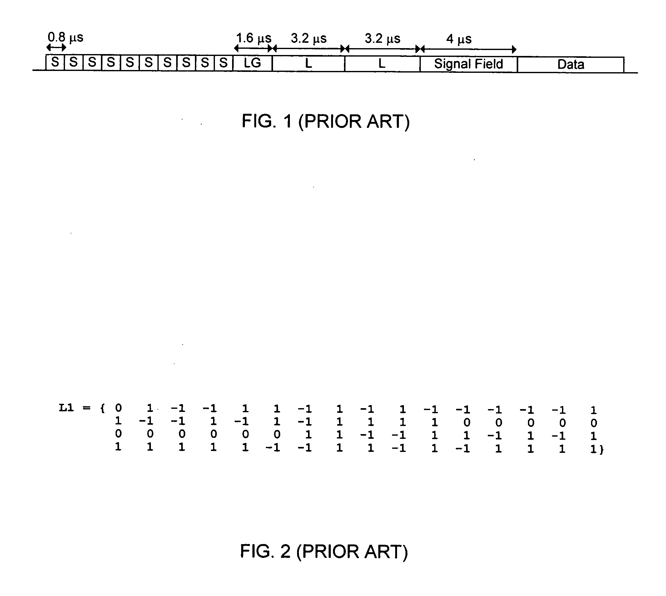
[0031] The EEE 802.11a standard defines a 20 microsecond long preamble with a structure as shown in FIG. 1, having short training symbols S (0.8 microseconds each), a guard interval LG, long training symbols L (3.2 microseconds each) and a signal field (4 microseconds). The ...


PUM


Abstract

A modified preamble is used by extended devices that operate in mixed mode environments and green field environments, to accommodate beamforming of transmissions. In one process, an extended wireless device processes data for transmission of that data as a packet, wherein the extended wireless device is a device configured to communicate using a standard protocol understood by each node device and an extended protocol not understood by legacy node devices. If the packet is to be directed at an extended device, the extended wireless device sends a preamble of that packet that is usable in an extended mode at extended devices and usable at a receiving legacy device to determine that the receiving legacy device is not the destination of data to follow the preamble. Once the receiving legacy device is expected to be deferring the network, the extended wireless device can beamform its signal or otherwise vary from the legacy protocol in communications with extended devices.

Description

CROSS-REFERENCE TO RELATED APPLICATIONS [0001] The present application also claims benefit under 35 USC §119(e) of U.S. provisional application No. 60 / 651,292, filed Feb. 8, 2005, entitled “Wireless Messaging Preambles Allowing for Beamforming and Legacy Device Coexistence”, the content of which is incorporated herein by reference in its entirety for all purposes. [0002] U.S. Pat. No. [U.S. patent application Ser. No. 11 / 140,349, filed May 27, 2005, entitled “Modified Preamble Structure for IEEE 802.11 A Extensions to Allow for Coexistence and Interoperability Between 802.11A”], to Gardner et al. (hereinafter “Gardner”), assigned commonly with the present application, is incorporated herein by reference in its entirety for all purposes. BACKGROUND OF THE INVENTION [0003] Wireless networks have become increasingly popular, as computers and other devices can be coupled for data communications without requiring wired connections between the network nodes. One set of standards for wirel...

Claims


Application Information

Patent Timeline
IPC IPC(8): H04J3/22H04J3/16H04B7/00
CPCH04L7/041H04W16/28H04W28/06H04W28/18H04W80/00H04W99/00H04L2027/0095
Inventor JONES, VINCENT K.VAN NEE, D.J. RICHARDVAN ZELST, ALBERT
Owner QUALCOMM INC
Learn More