
Worm gear drive aiming and locking mechanism

a technology of worm gear drive and aiming mechanism, which is applied in the direction of fixed installation, lighting and heating apparatus, lighting support devices, etc., can solve the problems of affecting the safety of placing a hand on or near the lamp, recessed downlight fixtures that fail to provide easy adjustment of luminaire pattern, and provide very little space for positioning a hand

Inactive Publication Date: 2006-08-31
PHILIPS LIGHTING NORTH AMERICA CORPORATION
View PDF32 Cites 49 Cited by
  • Summary
  • Abstract
  • Description
  • Claims
  • Application Information

AI Technical Summary

Benefits of technology

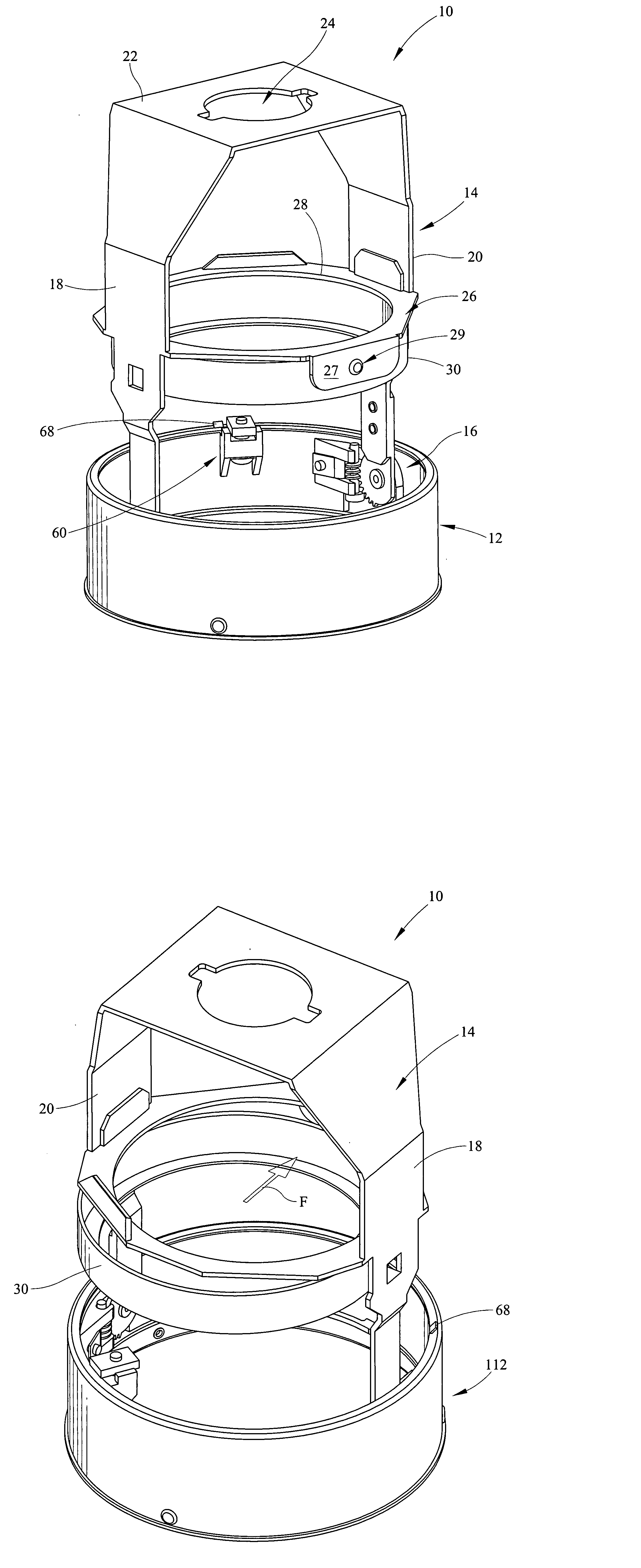
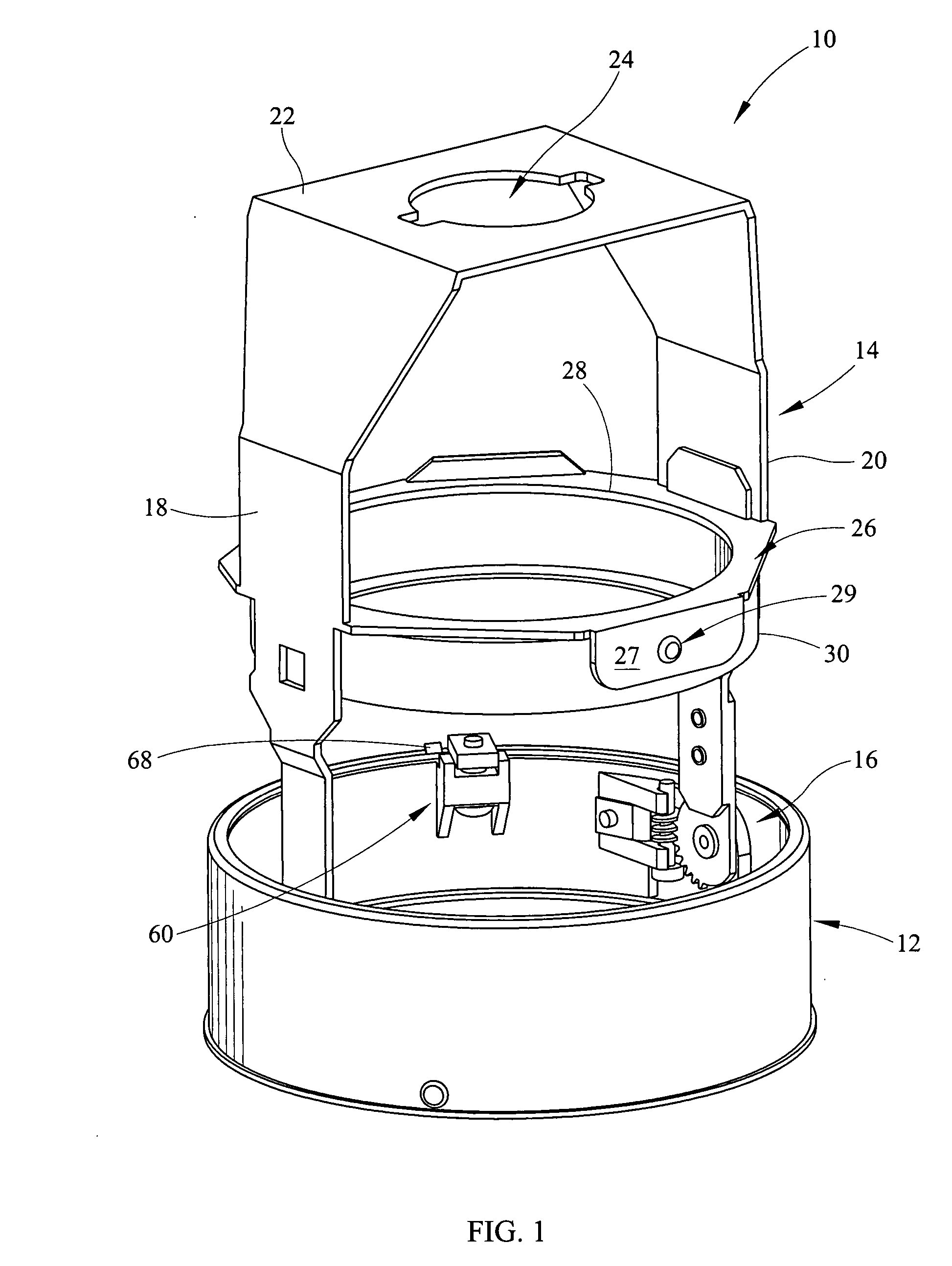
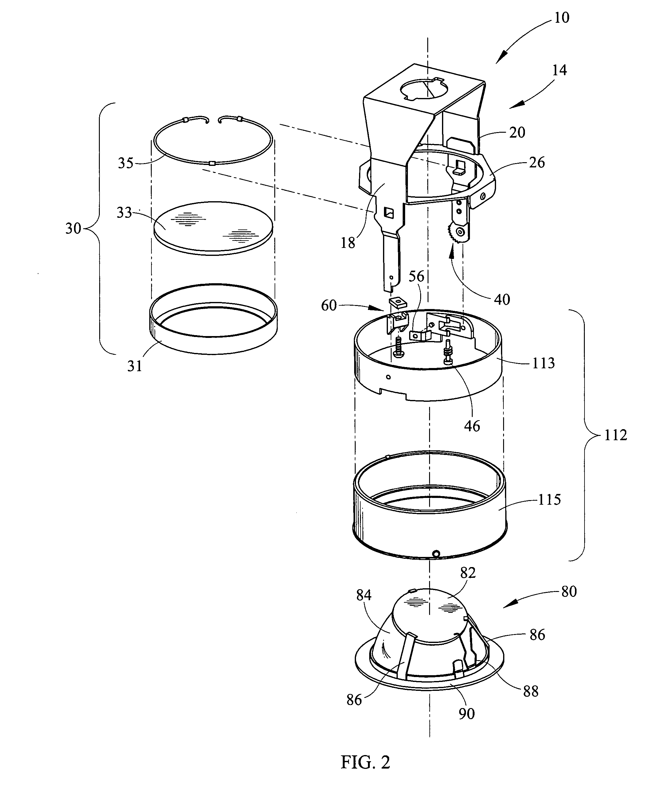
[0010] According to a one embodiment of the instant invention an adjustable downlight assembly comprises a collar, a yoke adjustable through an arcuate distance, the yoke pivotally connected to the collar, and a worm gear drive assembly operably engaging the yoke and the collar for pivoting the yolk about a horizontal axis. The worm gear drive assembly comprises a worm and a gear. The worm gear drive assembly is adjustable by rotation of the worm. The adjustable downlight assembly further comprises a biasing member fastened to a casting, the casting extending from an inner surface of the collar. The worm gear drive assembly inhibits unintentional movement of the yoke after adjustment is completed.

Problems solved by technology

Prior art recessed downlight fixtures fail to provide easy adjustment of the luminaire pattern.
For example, many fixtures require adjustment by hand that can lead to skin contact with heated elements of the lighting fixture, and resulting in burns.
When high intensity discharge lamps are utilized, placing a hand on or near the lamp is hazardous due to the high temperatures of the bulbs.
Further, due to the size of the fixtures, most lighting trims provide very little room for positioning of a hand in order to adjust or aim the light pattern.
Also prior art adjustment mechanisms may result in misalignment as a result of unsmooth or unstable adjustment mechanisms.
Finally, prior art adjustable fixtures often times fail to maintain an adjusted position once the aiming process is complete.
This results in aiming processes which take longer or repeated processes, which waste both time and money.
Thus there is a need for a fixture which allows aiming by a user without a hand being in close proximity to a lamp, which further allows adjustment or aiming without blocking the output light, and which does not allow the fixture to become misaligned after aiming is complete.

Method used


Image

  • Worm gear drive aiming and locking mechanism
  • Worm gear drive aiming and locking mechanism
  • Worm gear drive aiming and locking mechanism

Examples


Embodiment Construction

[0021] It should be understood that the invention is not limited in its application to the details of construction and the arrangement of components set forth in the following description or illustrated in the drawings. The invention is capable of other embodiments and of being practiced or of being carried out in various ways. Also, it is to be understood that the phraseology and terminology used herein is for the purpose of description and should not be regarded as limiting. The use of “including,”“comprising,” or “having” and variations thereof herein is meant to encompass the items listed thereafter and equivalents thereof as well as additional items. Unless limited otherwise, the terms “connected,”“coupled,” and “mounted,” and variations thereof herein are used broadly and encompass direct and indirect connections, couplings, and mountings. In addition, the terms “connected” and “coupled” and variations thereof are not restricted to physical or mechanical connections or couplin...


PUM


Abstract

According to a one embodiment of the instant invention an adjustable downlight assembly comprises a collar, a yoke adjustable through an arcuate distance, the yoke pivotally connected to the collar, and a worm gear drive assembly operably engaging the yoke and the collar for pivoting the yolk about a horizontal axis. The worm gear drive assembly comprises a worm and a gear. The worm gear drive assembly is adjustable by rotation of the worm. The adjustable downlight assembly further comprises a biasing member fastened to a casting, the casting extending from an inner surface of the collar. The worm gear drive assembly inhibits unintentional movement of the yoke after adjustment is completed.

Description

CROSS REFERENCES TO RELATED APPLICATIONS [0001] None. STATEMENT REGARDING FEDERALLY SPONSORED RESEARCH OR DEVELOPMENT [0002] None. REFERENCE TO SEQUENTIAL LISTING, ETC. [0003] None. BACKGROUND [0004] 1. Field of the Invention [0005] The present invention provides a worm gear drive aiming mechanism for a recessed downlight fixture. More specifically, the present invention comprises an aiming mechanism for a recessed downlight fixture as well as a rotation mechanism and locking mechanism for the rotation mechanism on the fixture. [0006] 2. Description of the Related Art [0007] Recessed downlight fixtures have become increasingly popular for residential and commercial use. One reason for the increased popularity is that the recessed downlight fixtures is that they meet a wide range of interior lighting requirements while also being aesthetically pleasing. Further these recessed downlight fixtures may be installed in new constructions as well as existing ceilings. Typically, ceiling-mou...

Claims


Application Information

Patent Timeline
Patent Type & Authority Applications(United States)
IPC IPC(8): F21S8/08
CPCF21S8/026F21V21/30F21V17/168F21V9/08
Inventor DUPRE, SCOTT
Owner PHILIPS LIGHTING NORTH AMERICA CORPORATION
Learn More