Communication apparatus
- Summary
- Abstract
- Description
- Claims
- Application Information
AI Technical Summary
Benefits of technology
Problems solved by technology
Method used
Image
Examples
first embodiment
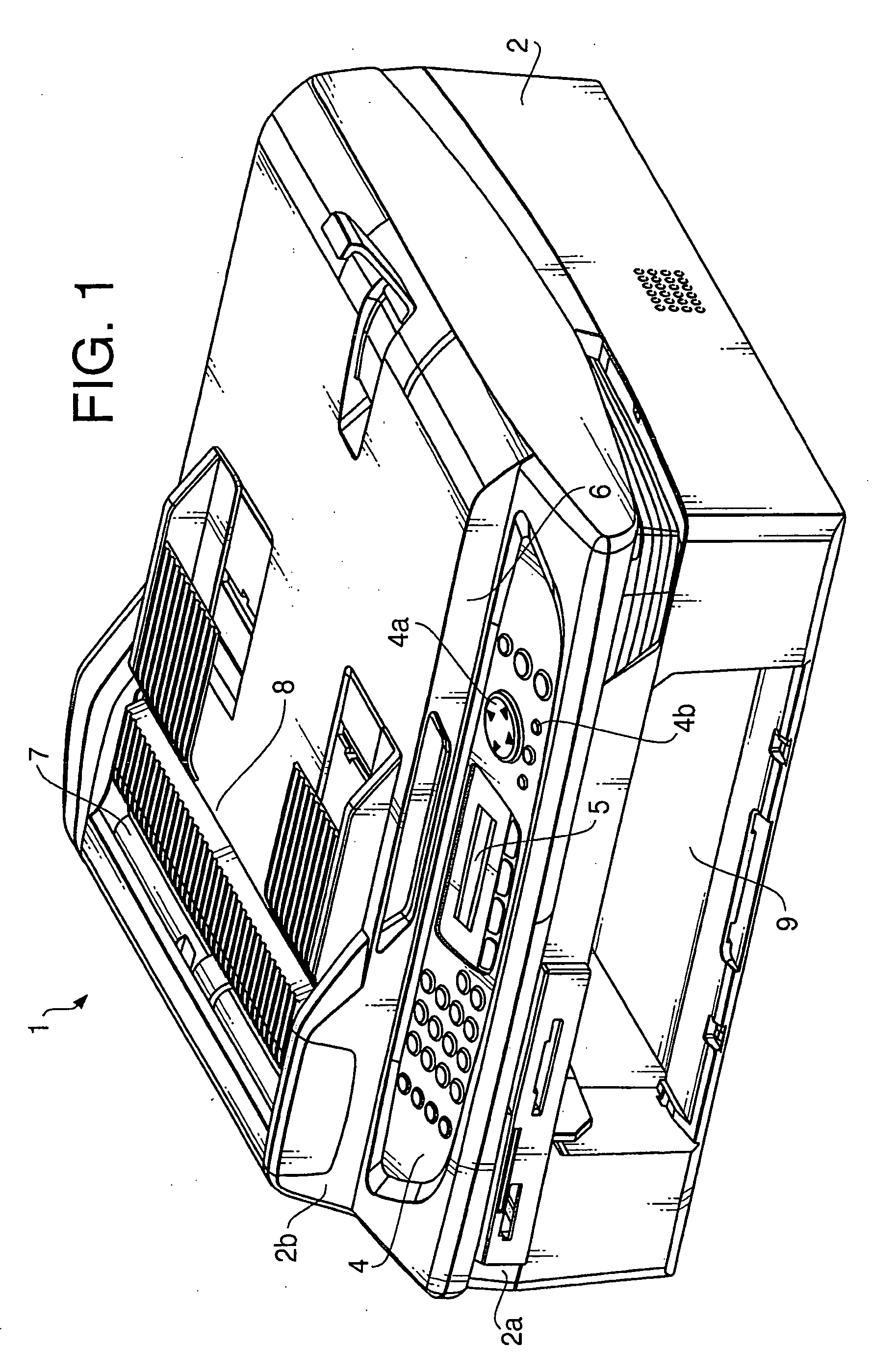
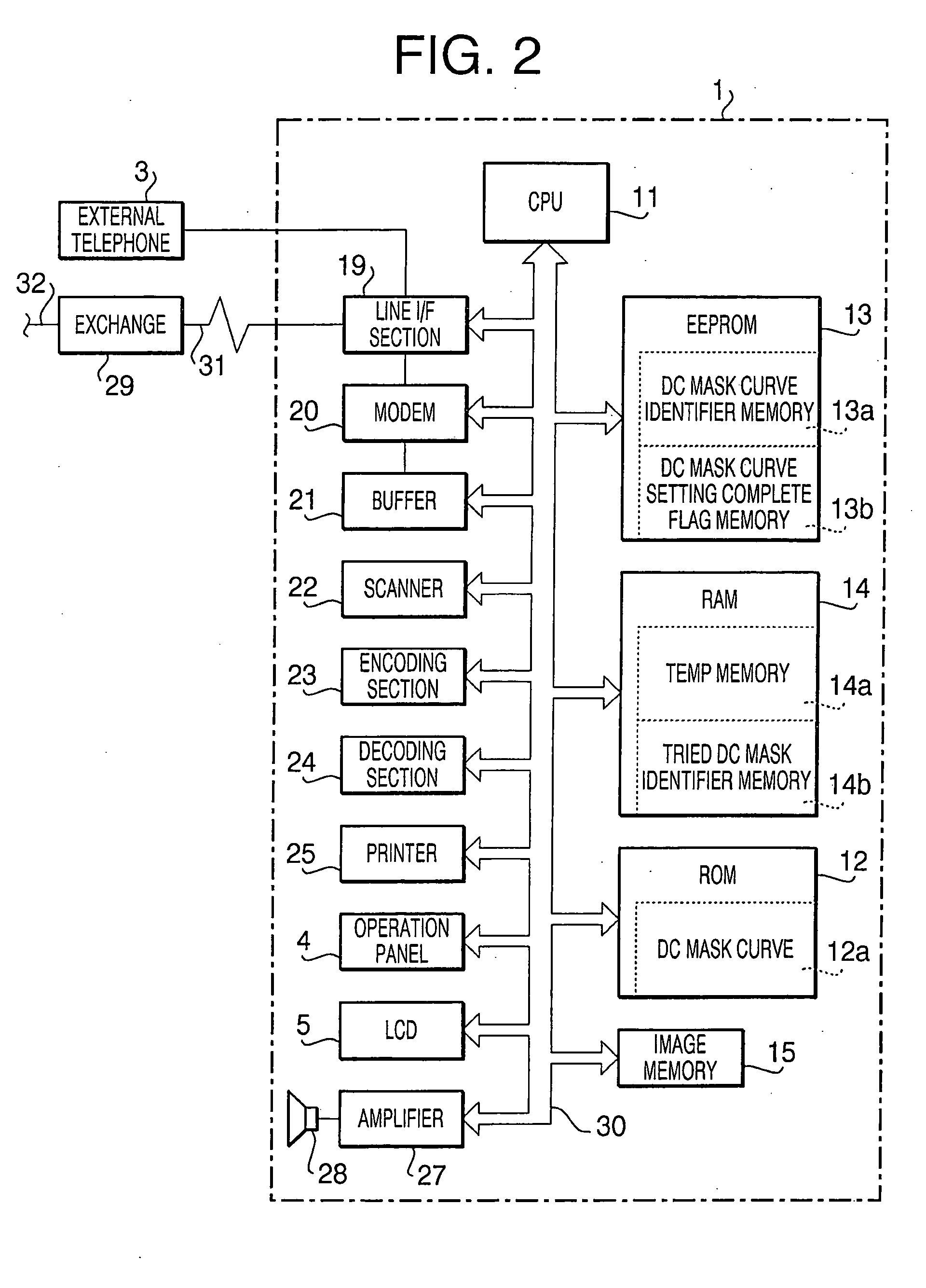
[0038]FIG. 1 is a perspective view of a communication apparatus 1 according to aspects of the invention. The communication apparatus 1 is an MFP (Multi Function Peripheral) which has multiple functions such as functions of a facsimile machine, a copier, a scanner, a telephone, etc. The main unit 2 has an upper body portion 2b and a bottom portion 2a. The upper body portion 2b is attached to the bottom portion 2a such that the upper body portion 2b is moved between open / closed positions with respect to the bottom portion 2a. Further, a printer 25 is built in the bottom portion 2a as shown in FIG. 2.
[0039] An operation panel 4 is formed on the front side of the upper body portion 2b. The operation panel 4 includes switches to control multiple functions of the facsimile machine, copier, scanner, etc., numeric keys to input numerals, a cursor key 4a to move a cursor displayed on a display unit 5, a confirm key (enter key) 4b which is to be pressed by a user for confirmation of input set...
second embodiment
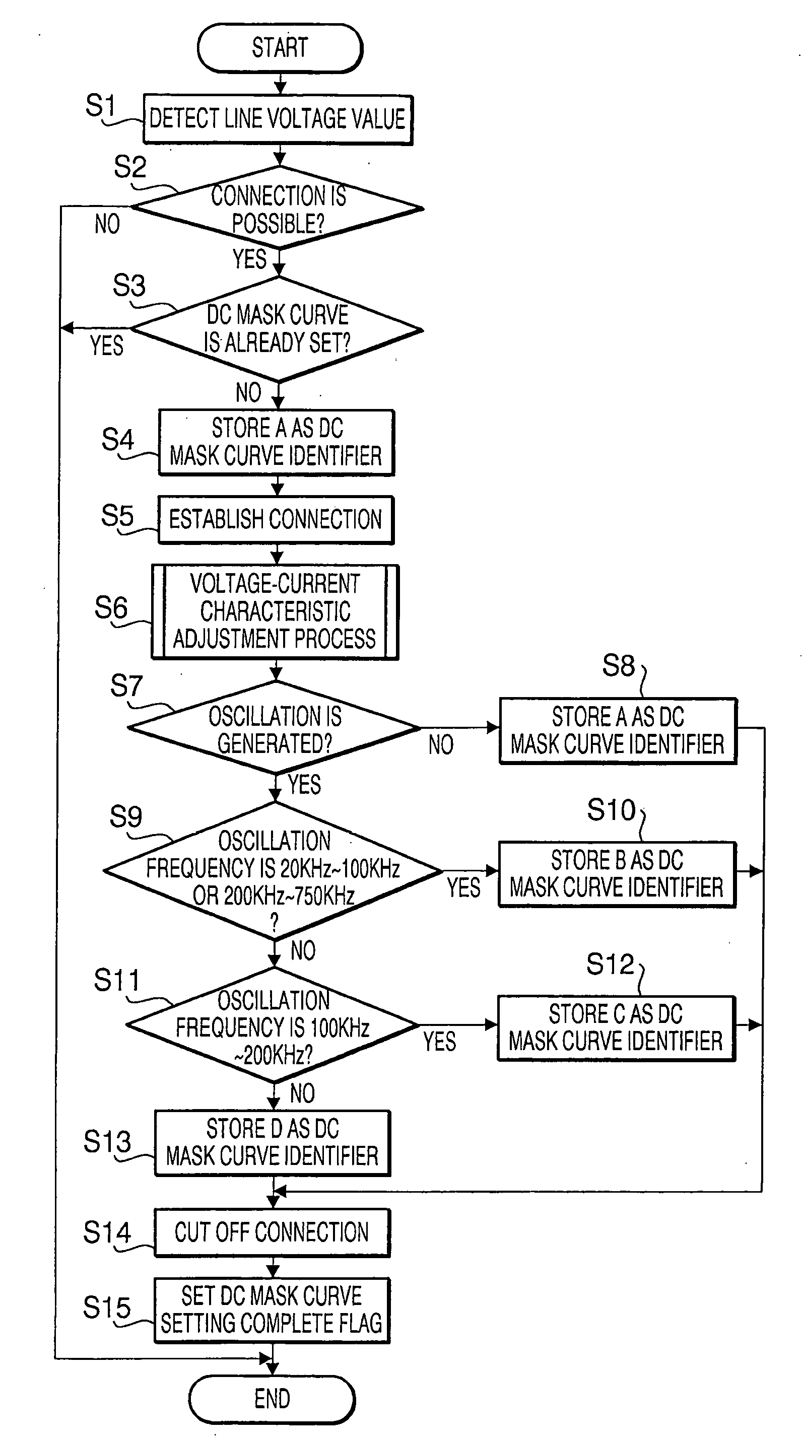
[0086] Next, the DC mask curve setting process will be described with reference to the flowchart shown in FIG. 7. The process is executed when the communication apparatus 1 is powered on.
[0087] First, the line voltage value detected by the voltage detection circuit 34 is checked (S21). Then, it is judged whether the line voltage value is equal to or greater than the minimum voltage which allows the communication apparatus 1 to connect with the communication line network (S22). If the line voltage is equal to or greater than the minimum voltage (Yes at S22), the DC mask curve setting complete flag memory 13b of EEPROM 13 is checked, and it is judged whether the DC mask curve has already been set (S23). If a DC mask curve has not been set (No at S23), the identifier A is stored in the Temp memory 14a (S24), and the connection with the network is cut (S25). Next, the voltage-current characteristic adjustment process shown in FIG. 11 is executed (S26), and the line voltage and the line...
third embodiment
[0094]FIG. 8 is a flowchart showing the DC mask curve setting process according to the The process is executed when the communication apparatus 1 is powered on.
[0095] First, the line voltage value detected by the voltage detection circuit 34 is checked (S41). Then, it is judged whether the line voltage value is equal to or greater than the minimum voltage which allows the communication apparatus 1 to connect with the communication line network (S42). If the line voltage is equal to or greater than the minimum voltage (Yes at S42), the DC mask curve setting complete flag memory 13b of EEPROM 13 is checked, and it is judged whether the DC mask curve has already been set (S43). If the DC mask curve has not been set (No at S43), the identifier A is stored in the Temp memory 14a (S44), and the connection with the network is cut (S45). Next, the voltage-current characteristic adjustment process (see FIG. 11) is executed (S46). In the voltage-current characteristic adjustment process, the...
PUM
 Abstract
Description
Claims
Application Information
 - R&D Engineer
- R&D Manager
- IP Professional
- Industry Leading Data Capabilities
- Powerful AI technology
- Patent DNA Extraction
Browse by: Latest US Patents, China's latest patents, Technical Efficacy Thesaurus, Application Domain, Technology Topic, Popular Technical Reports.
© 2024 PatSnap. All rights reserved.Legal|Privacy policy|Modern Slavery Act Transparency Statement|Sitemap|About US| Contact US: help@patsnap.com


