
Modular heated cover

Active Publication Date: 2006-08-31
GREENHEAT IP HLDG LLC
View PDF42 Cites 26 Cited by
  • Summary
  • Abstract
  • Description
  • Claims
  • Application Information

AI Technical Summary

Benefits of technology

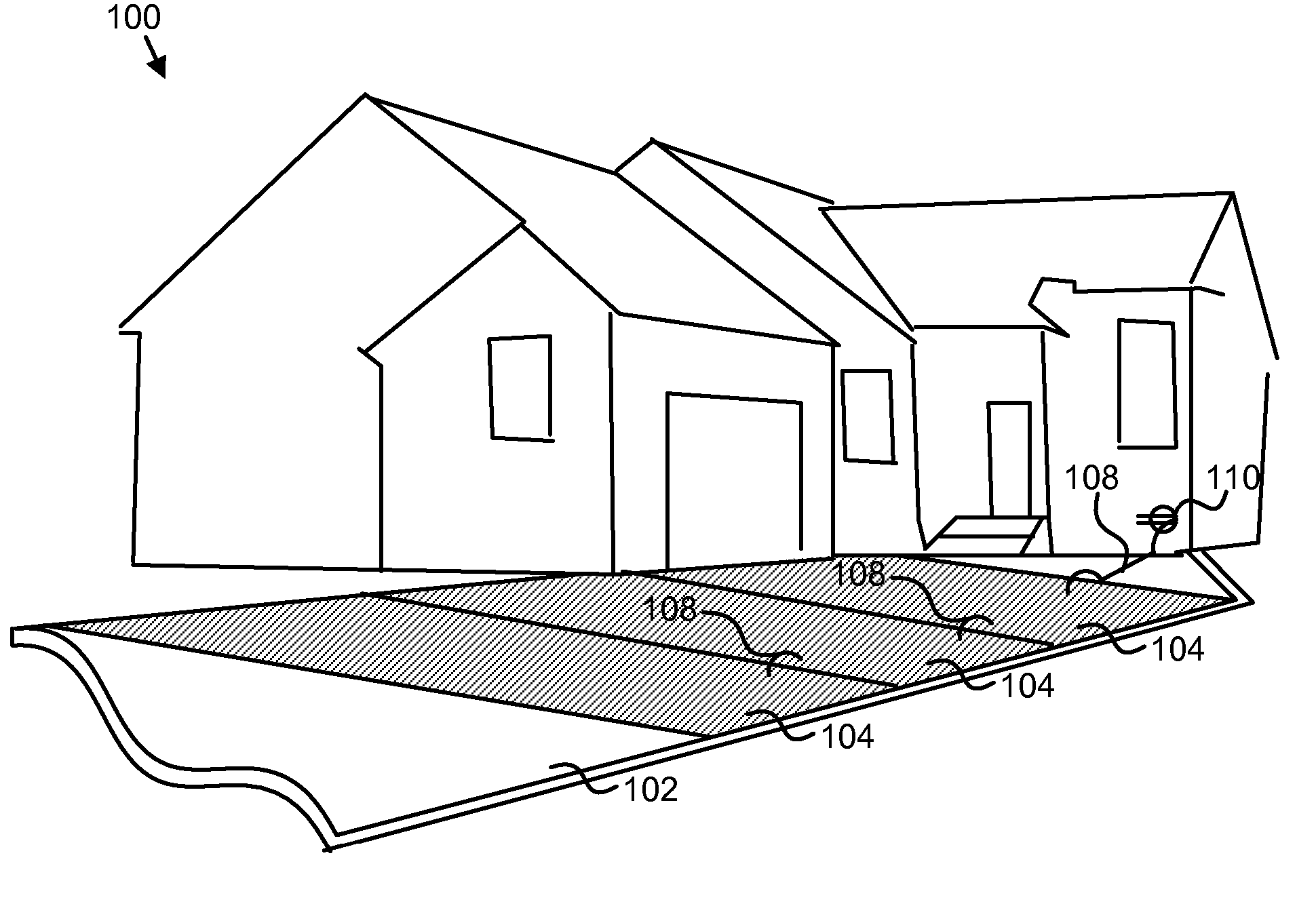
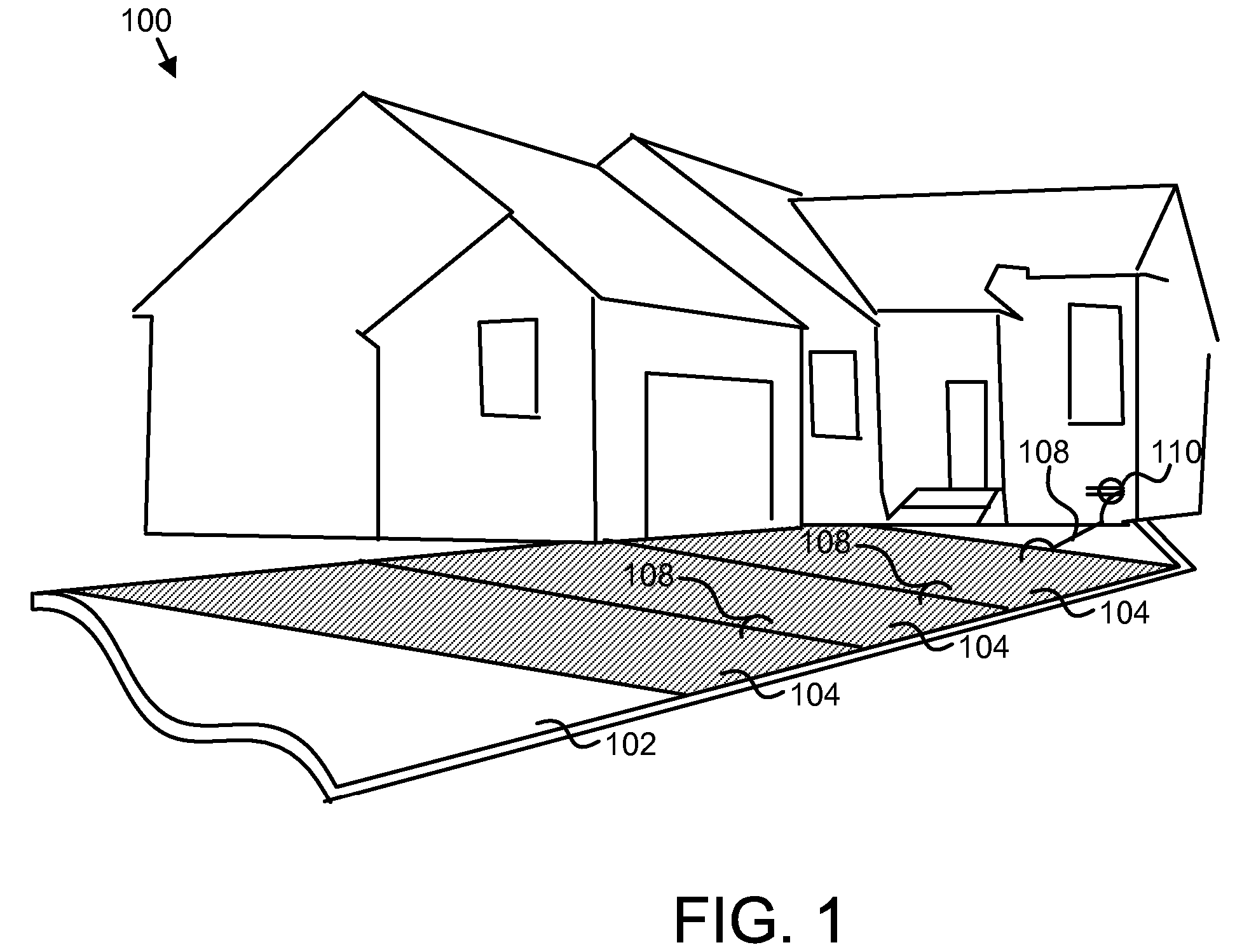
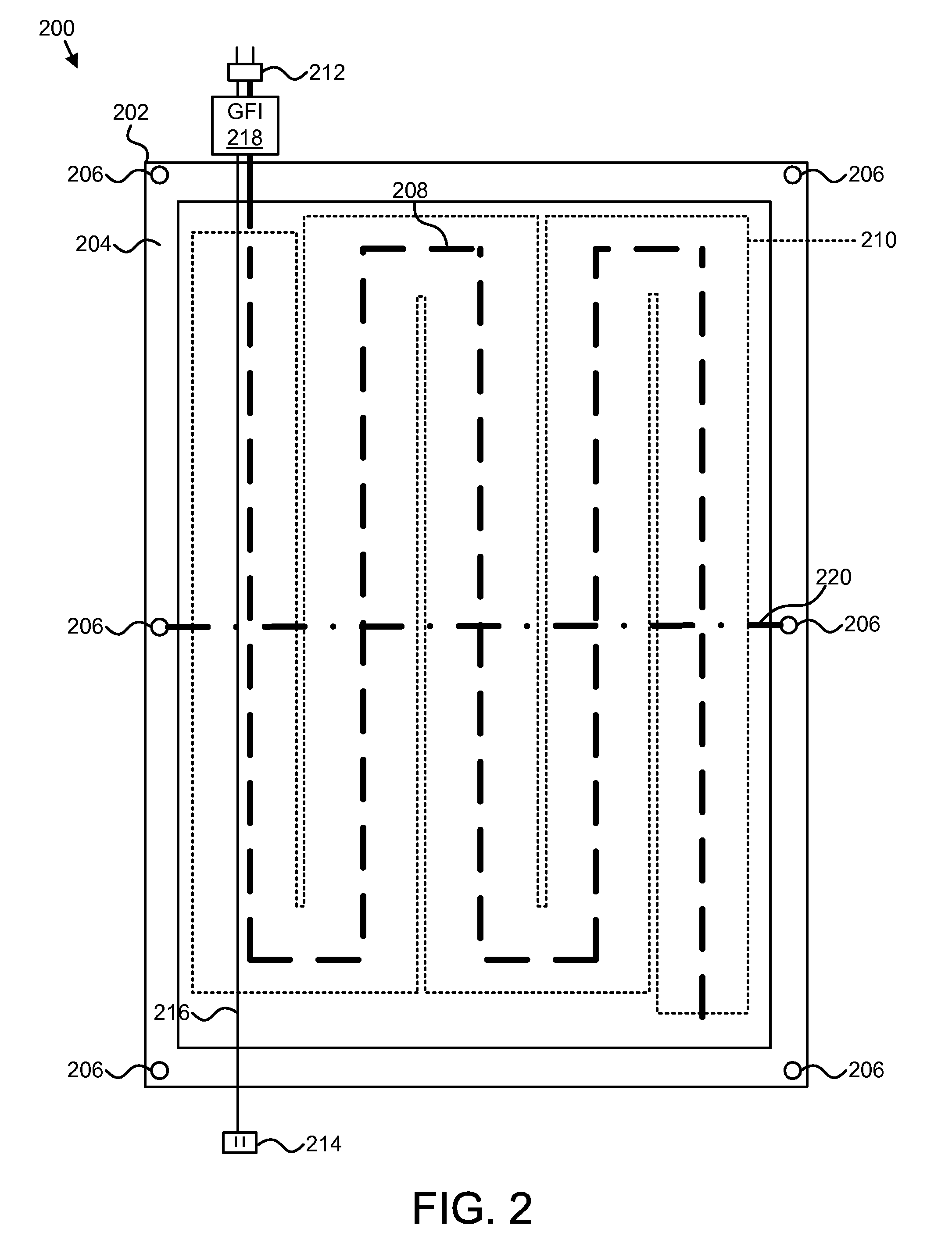
[0019] Alternative embodiments of the modular heated cover may include a top layer and a bottom layer, wherein the top and bottom layers provide durable protection in an outdoor environment, a resistive element between the top and the bottom layers for converting electric current to heat energy, a planar heat spreading element in contact with the resistive element for distributing the heat energy generated by the resistive element, an air isolation flap configured to prevent heat loss to air circulation, an electrical power connection for obtaining electrical energy from a power source, and an electric power coupling for conveying electrical energy from a first modular heated cover to a second modular heated cover.

Problems solved by technology

Ice, snow and, frost create problems in many areas of construction.
Unfortunately, such methods are often expensive, time consuming, inefficient, and otherwise problematic.
In construction, ice buildup is particularly problematic.
For example, ice and snow may limit the ability to pour concrete, lay roofing material, and the like.
In these outdoor construction situations, time and money are frequently lost to delays caused by snow and ice.
If delay is unacceptable, the cost to work around the situation may be unreasonable.
This process is costly in material and labor.
In an outdoor environment where freezing temperatures exist or may exist, it is difficult to maintain adequate curing temperatures.
Conventional solutions for keeping driveways, overhangs, and the like clear of snow, typically require permanent fixtures that are both costly to install and operate, or small portable devices that do not cover sufficient surface area.
While some solutions are available for construction industries to thaw ground, keep ground thawed, and cure concrete, these solutions are large, expensive to operate and own, time consuming to setup and take down, and complicated.
Laying and arranging the hosing and cover can be time consuming.
Furthermore, heating and circulating the fluid requires significant energy in the form of heaters, pumps, and / or generators.
Currently, few conventional solutions exist that use electricity to produce and conduct heat.
Traditionally, this was due to limited circuit designs.
Traditional solutions were unable to produce sufficient heat over a sufficient surface area to be practical.
These special electrical circuits are often unavailable at a construction site.
Thus using conventional standard circuits, conventional solutions are unable to produce sufficient heat over a sufficiently large surface area to be practical.
Conventional electrically powered solutions are incapable of providing 143 BTUs over a sufficiently large enough area for practical use in the construction industry.
Consequently, the construction industry has turned to bulky, expensive, time consuming heated fluid solutions.

Method used


Image

  • Modular heated cover
  • Modular heated cover
  • Modular heated cover

Examples


Embodiment Construction

[0038] Reference throughout this specification to “one embodiment,”“an embodiment,” or similar language means that a particular feature, structure, or characteristic described in connection with the embodiment is included in at least one embodiment of the present invention. Thus, appearances of the phrases “in one embodiment,”“in an embodiment,” and similar language throughout this specification may, but do not necessarily, all refer to the same embodiment.

[0039] Furthermore, the described features, structures, or characteristics of the invention may be combined in any suitable manner in one or more embodiments. In the following description, numerous specific details are provided, such as examples of materials, layers, connectors, conductors, insulators, and the like, to provide a thorough understanding of embodiments of the invention. One skilled in the relevant art will recognize, however, that the invention may be practiced without one or more of the specific details, or with ot...


PUM


Abstract

The modular heated cover is disclosed with a first pliable outer layer and a second pliable outer layer, wherein the outer layers provide durable protection in an outdoor environment, an electrical heating element between the first and the second outer layers, the electrical heating element configured to convert electrical energy to heat energy, and a thermal insulation layer positioned above the active electrical heating element. Beneficially, such a device provides radiant heat, weather isolation, temperature insulation, and solar heat absorption efficiently and cost effectively. The modular heated cover quickly and efficiently removes ice, snow, and frost from surfaces, and penetrates soil and other material to thaw the material to a suitable depth. A plurality of modular heated covers can be connected on a single 120 Volt circuit protected by a 20 Amp breaker.

Description

CROSS-REFERENCES TO RELATED APPLICATIONS [0001] This application claims the benefit of U.S. Provisional Patent Application No. 60 / 654,702 entitled “A MODULAR ACTIVELY HEATED THERMAL COVER” and filed on Feb. 17, 2005 for David Naylor and U.S. Provisional Patent Application No. 60 / 656,060 entitled “A MODULAR ACTIVELY HEATED THERMAL COVER” and filed on Feb. 23, 2005 for David Naylor, and Provisional Patent Application No. 60 / 688,146 entitled “LAMINATE HEATING APPARATUS” and filed on Jun. 6, 2005 for David Naylor, which are incorporated herein by reference.FIELD OF THE INVENTION [0002] This invention relates to thermal covers and more particularly relates to modular heated covers configured to couple together. DESCRIPTION OF THE RELATED ART [0003] Ice, snow and, frost create problems in many areas of construction. For example, when concrete is poured the ground must be thawed and free of snow and frost. In agriculture, planters often plant seeds, bulbs, and the like before the last free...

Claims


Application Information

Patent Timeline
IPC IPC(8): H05B3/34H05B3/54
CPCE01C11/265E04G21/24H05B3/267H05B3/34H05B2203/003H05B2203/004H05B2203/013E04G21/246
Inventor NAYLOR, DAVID
Owner GREENHEAT IP HLDG LLC
Learn More