
Clutch apparatus

a technology of clamping device and clamping plate, which is applied in the direction of fluid coupling, gearing, interengaging clutch, etc., can solve the problems of inability to accumulate oversizes or undersizes, and the side housing wall or between the stator and the takeoff side housing wall becomes completely unnecessary, so as to avoid effective any tolerance-related problems

Inactive Publication Date: 2006-08-31
ZF FRIEDRICHSHAFEN AG
View PDF5 Cites 9 Cited by
  • Summary
  • Abstract
  • Description
  • Claims
  • Application Information

AI Technical Summary

Benefits of technology

The invention is about a clutch apparatus with a housing and a takeoff hub. The goal is to design the clutch in a way that eliminates any functional disadvantages and prevents tilting of the takeoff hub and support hub. The solution is to provide a stop element on the takeoff hub and a stop on the takeoff-side housing wall that work together to hold the takeoff hub in a precise position. This eliminates the need for an axial bearing between the takeoff hub and the takeoff-side housing wall. The maximum distance between the stops is set to ensure that the pressure-exerting means will not interfere with other parts in the clutch device. The design also allows for a compact stop element that can be easily produced.

Problems solved by technology

The use of an axial bearing directly between the takeoff hub and the takeoff-side housing wall or between the stator and the takeoff-side housing wall thus becomes completely unnecessary.
There are therefore very few points—in the most favorable case, only a single point—located axially between the drive-side housing wall and the takeoff-side housing wall which are subject to manufacturing tolerances, which means that it is impossible for oversizes or undersizes to accumulate to the point that they can cause trouble.

Method used


Image

  • Clutch apparatus
  • Clutch apparatus
  • Clutch apparatus

Examples


Embodiment Construction

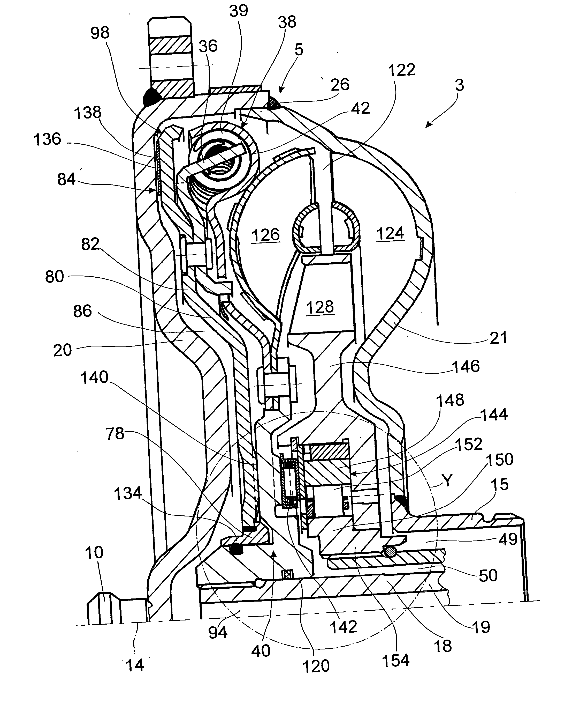
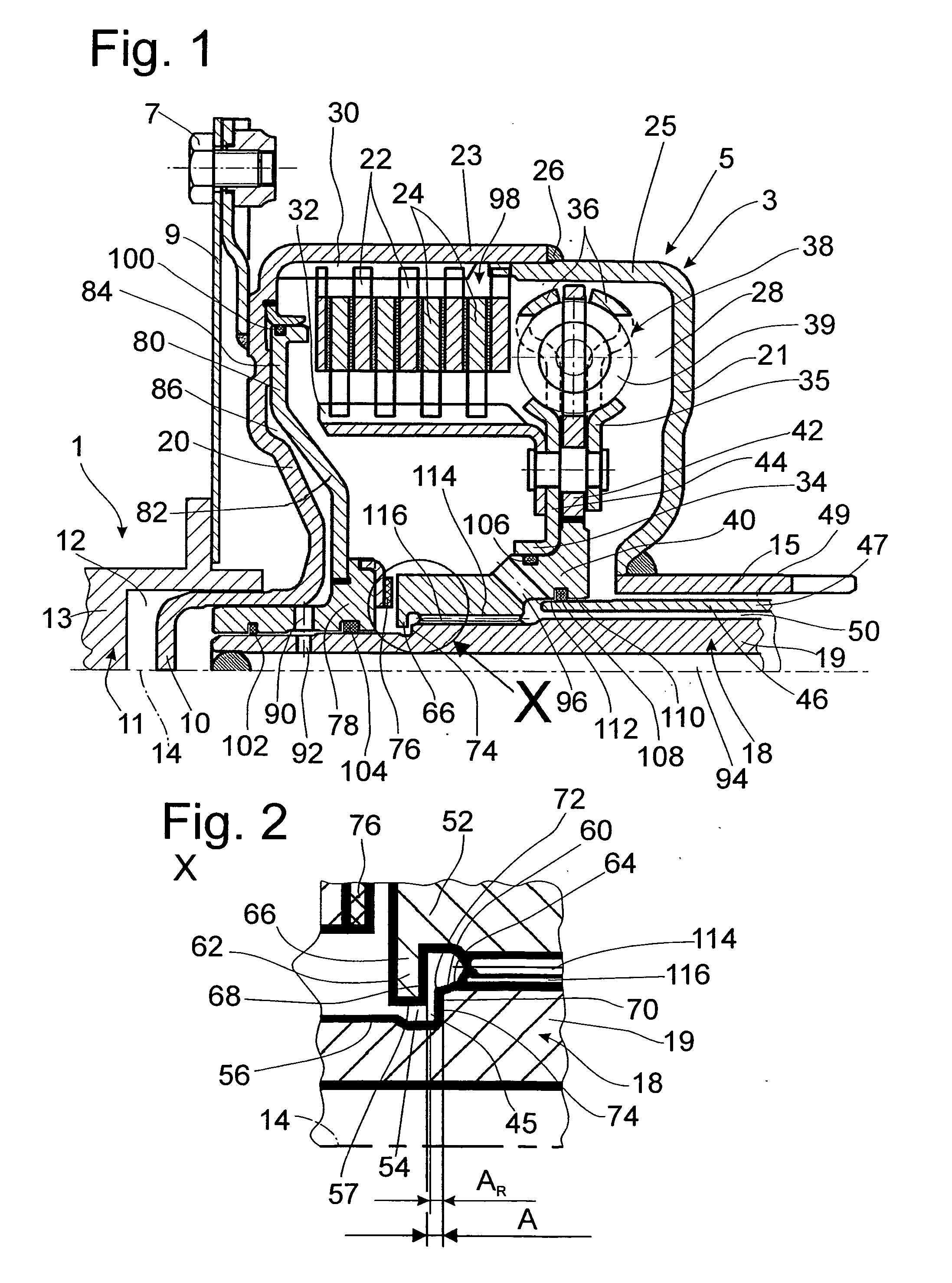
[0029]FIG. 1 shows a schematic diagram of a drive train 1 with an inventive clutch device 3. The clutch device 3 includes a housing 5, which can be connected for rotation in common by means of a plurality of fastening elements 7 and a connecting element 9 such as a flexplate to a drive 11, such as the crankshaft 13 of an internal combustion engine. In the area of the axis of rotation 14, the clutch device has a bearing journal 10, which is mounted in a centering guide 12, formed on the drive 11. On the axial side away from the drive 11, the housing 5 has a housing hub 15, which is connected, for example, to a transmission arrangement (not shown), where it causes a fluid delivery pump (also not shown) to rotate. Mounted concentrically to the housing hub 15 is a takeoff 18, the free end of which projects into the housing 5. This takeoff 18 can be, for example, a gearbox input shaft 19.

[0030] The housing 5 has a drive-side housing wall 20, which extends from the bearing journal 10 ess...


PUM


Abstract

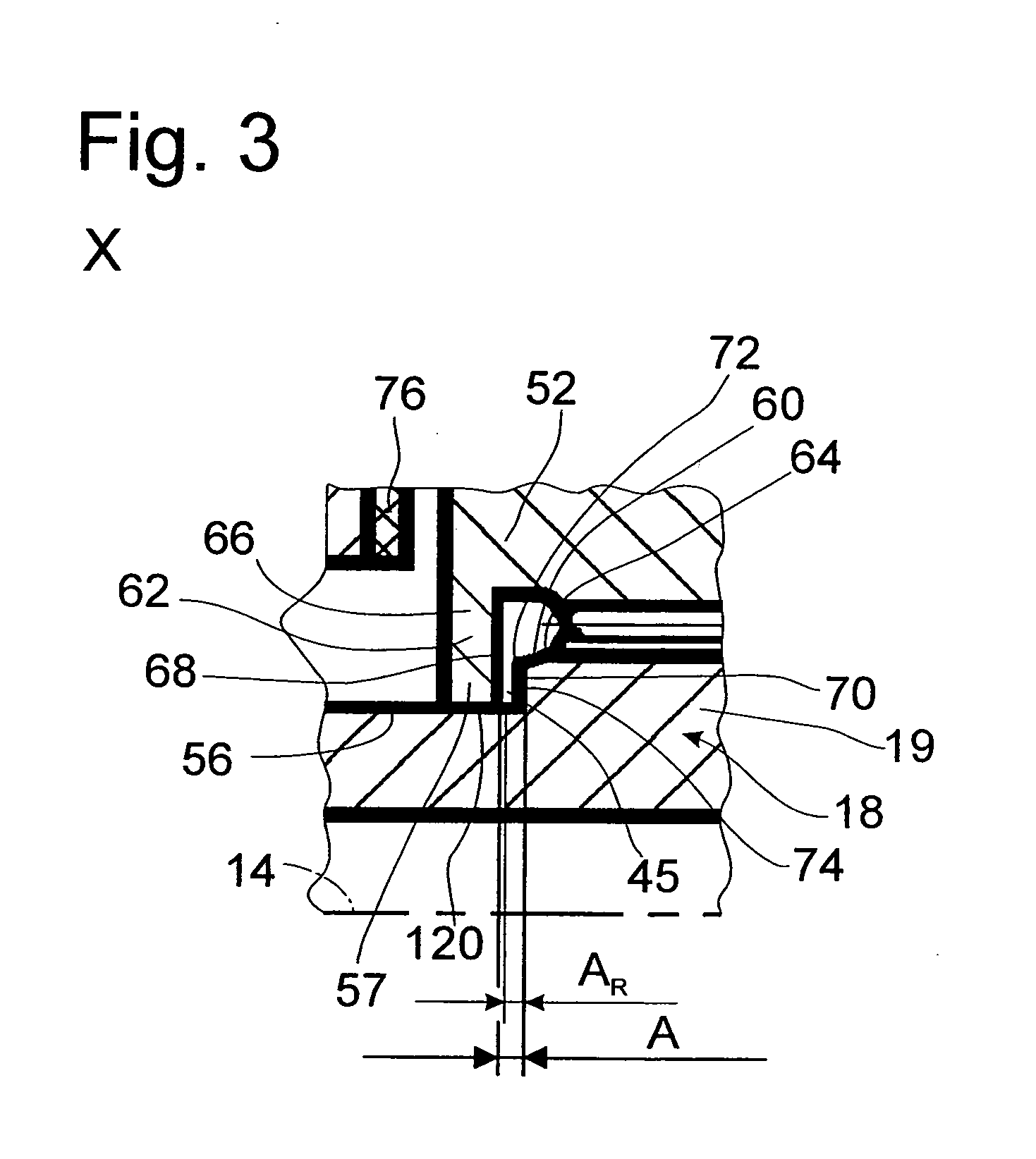
A clutch apparatus includes a drive; a housing connected to the drive for rotation in common; a takeoff which can rotate relative to the housing, the takeoff having an axial stop; and a takeoff hub connected to the takeoff for rotation in common, the takeoff hub having an axial stop element and being axially movable relative to the takeoff. A friction clutch mounted in the housing and includes at least one first clutch element connected to the housing for rotation in common, at least one second clutch element connected to the takeoff hub for rotation in common, and means for exerting pressure to shift the clutch from a first position to a second position, wherein the first and second clutch elements are frictionally engaged in one of the positions and disengaged in the other of the positions. The stop element and the stop are separated by a gap A defining a maximum distance in the first position, the gap A being at least partially closed in the second position.

Description

BACKGROUND OF THE INVENTION [0001] 1. Field of the Invention [0002] The invention pertains to a clutch apparatus including a drive, a housing connected to the drive for rotation in common, a takeoff which can rotate relative to the housing, a takeoff hub connected to the takeoff for rotation in common and being axially movable relative to the takeoff, and a friction clutch mounted in the housing. The clutch has at least one first clutch element connected to the housing for rotation in common, at least one second clutch element connected to the takeoff hub for rotation in common, and means for exerting pressure to shift the clutch from a first position to a second position. The first and second clutch elements are frictionally engaged in one of the positions and disengaged in the other of the positions. [0003] 2. Description of the Related Art [0004] A clutch device of this type is known from DE 103 15 169 A1. This device has a housing with a drive such as the crankshaft of an intern...

Claims


Application Information

Patent Timeline
Patent Type & Authority Applications(United States)
IPC IPC(8): F16H45/02
CPCF16D25/0638F16H45/02F16H2041/246F16H2045/0205F16H2045/0284F16H2045/0294
Inventor SCHRODER, ARTHUR
Owner ZF FRIEDRICHSHAFEN AG
Learn More