
Moving device and open/close control device for moving body

a technology of moving body and control device, which is applied in the direction of instruments, wing accessories, fluid pressure measurement, etc., can solve the problems of door closing operation continuing without detection, another part of the human body making unnecessary contact with the sliding door or being caught, and achieving the effect of increasing safety

Inactive Publication Date: 2006-08-31
PANASONIC CORP
View PDF0 Cites 21 Cited by
  • Summary
  • Abstract
  • Description
  • Claims
  • Application Information

AI Technical Summary

Benefits of technology

"The invention is a system that stops or controls the movement of a moving body when it detects contact or removal of an object using an object detecting means. This increases safety, especially when the object is soft or the moving body is slow. The system uses a flexible piezoelectric sensor that detects vibrations of the moving body and is fed when the engine is stopped. This ensures detection of collisions and catching of objects between the moving body and the vehicle body while suppressing dark current."

Problems solved by technology

However, in the conventional moving device described in Patent Document No. 1, the object that makes contact with the pressure sensor is soft like the hand of a human body, since the object is pressed to be deformed when the pressure sensor 3 makes contact with the object in the middle of the closure of the sliding door, a sufficient pressure is not applied to the pressure sensor 3, leading to the occurrence of a situation where the door closing operation continues with no detection of contact with the object.
However, since the sliding door 2 continues the closing operation even after the removal of the object until the pressure sensor 3 detects a contact, for example, in a case where a human body exists in the vicinity of the sliding door 2, even in the event that the hand is removed from the pressure sensor 3, there has existed a problem that another part of the human body makes unnecessary contact with the sliding door or is caught thereby.
In addition, in the conventional moving device described in Patent Document No. 2, for example, when a door closing operation is started in such a state that an object such as the hand of the human body is in contact with the periphery of the tailgate, in the event that the contact location is in the vicinity of an upper part of the tailgate, that is, a location near the center of rotation, since the moving speed is slow, a sufficient pressure to cause the electrodes of the pressure sensor to make contact with each other is not applied as long as the hand is unnaturally pressed against the door, leading to the occurrence of a situation where the door closing operation continues while the pressure sensor cannot detect the contact with the hand.
Due to this, to avoid the catching of the object between the body and the pressure sensor, as with the conventional moving device described in Patent Document No. 1, while the object may be removed from the pressure sensor before it is so caught, since the tailgate continues the door closing operation even after the removal of the object as long as the pressure sensor does not detect the contact, for example, when the human body exists under the tailgate being closed, even in the event that the hand is removed from the pressure sensor, there has existed a problem that the head or the like of the human body is unnecessarily struck by the tailgate.
In addition, there is also an increasing tendency that female drivers drive vehicles of such types which are tall in height, and the difficulty they experience when attempting to manually open and close a heavy sliding door or a tailgate which is opened to a high position constitutes one of the background reasons.
In these conventional moving body opening and closing control systems, however, there remains a trouble resulting when the tailgate is opened.
Namely, accidents could not be avoided by the tailgates in which a human body collides with the tailgate and in which the tailgate collides with a wall or ceiling of a structure such as a building while a tailgate opening operation is performed.
In addition, since the pressure sensor 110 and the computer 102 are supplied with power from the battery 105, there is caused a problem that no control is implemented on the suppression of dark current (power that is consumed while the engine is stopped) when the engine is deactivated.

Method used


Image

  • Moving device and open/close control device for moving body
  • Moving device and open/close control device for moving body
  • Moving device and open/close control device for moving body

Examples


embodiment 1

[0058] An invention according to Embodiment 1 will be described by reference to FIGS. 1 to 5 and 7. In Embodiment 1, a moving device of the invention will be described as being applied to a sliding door of an automobile.

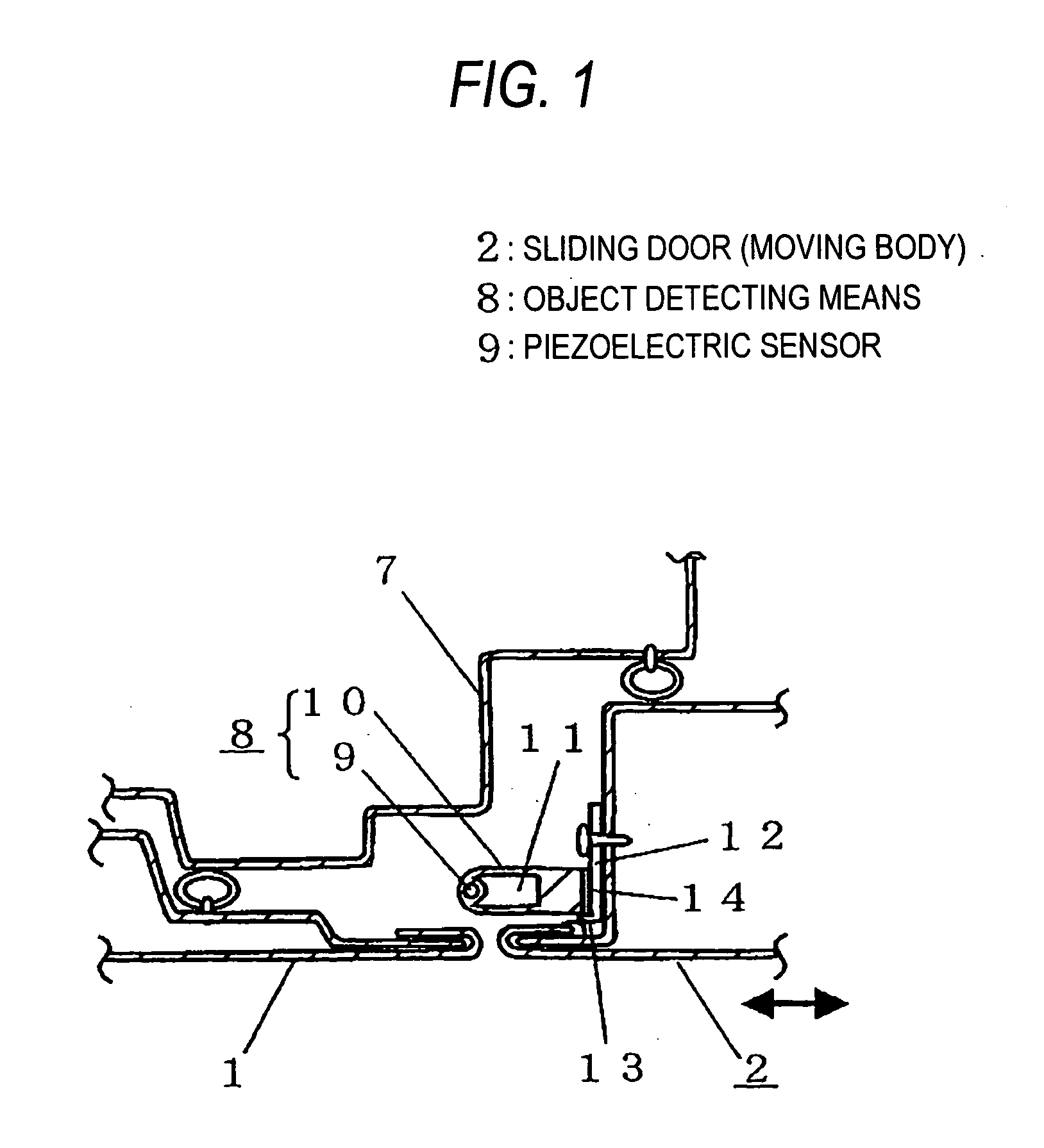
[0059]FIG. 1 is a sectional view of a moving device of Embodiment 1 at a position corresponding to the line A-A in FIG. 7. FIG. 1 shows a state in which a sliding door is closed completely, and an upper side of the drawing denotes an inside of a vehicle, whereas a lower side thereof denotes an outside thereof.

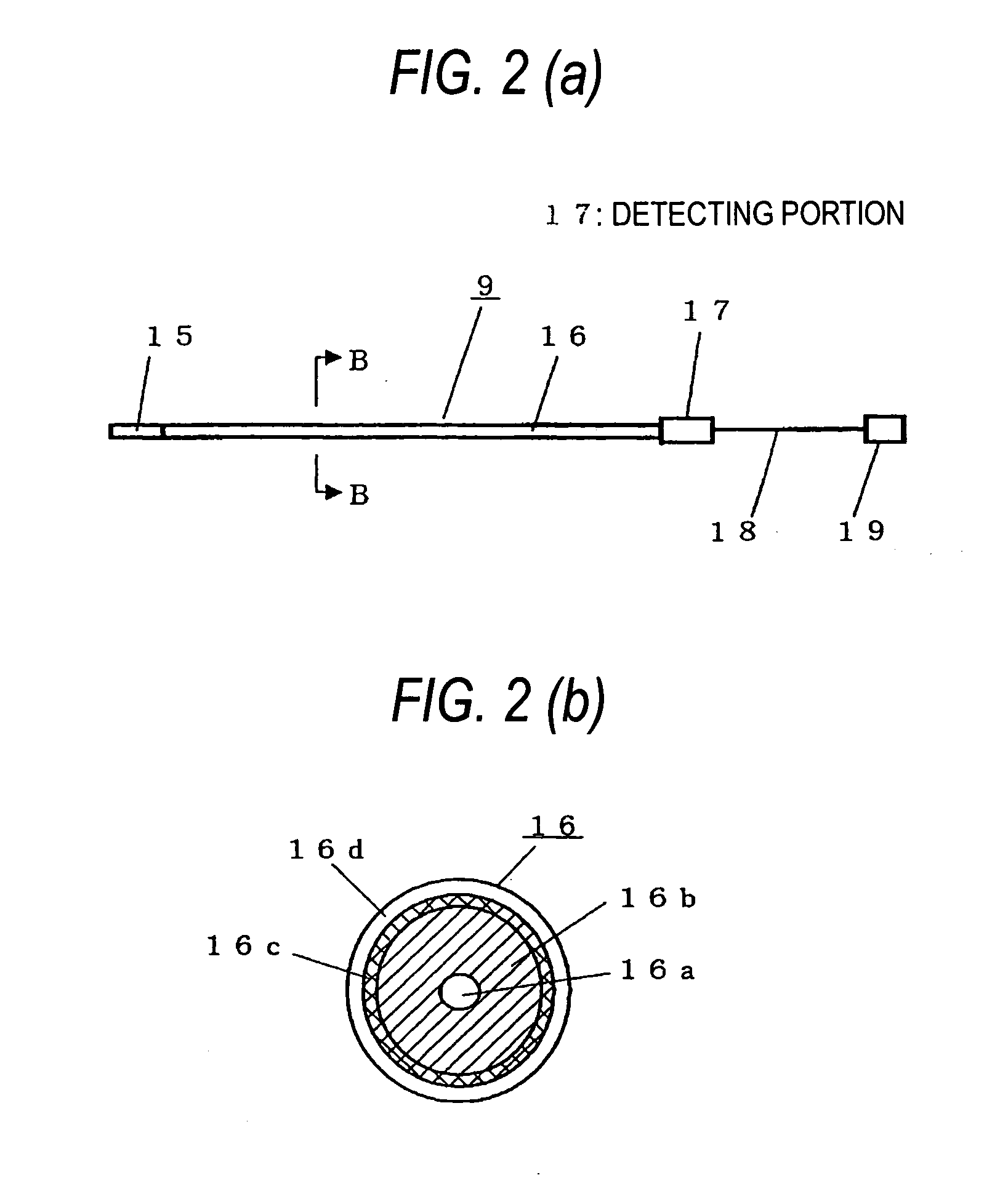
[0060] Firstly, the configuration of the moving device of Embodiment 1 will be as follows. In FIG. 1, reference numeral 1 denotes a body portion of a vehicle body (an end portion of a door at a side of a front passenger seat in FIG. 7), and 2 denotes a sliding door as a moving body. Reference numeral 7 denotes a main structure of the vehicle body and 8 denotes a contact detecting means, which has a piezoelectric sensor 9 which is flexible and which takes the f...

embodiment 2

[0090] An invention according to Embodiment 2 will be described by reference to FIG. 6. FIG. 6 is an external view showing a moving device of Embodiment 2. Points in which Embodiment 2 differs from Embodiment 1 are that a moving body is a running vehicle 24 having bumpers 23 and that the object detecting means 8 is provided in the bumpers 23.

[0091] In this configuration, when the object detecting means 8 detects a contact of an object or a removal of the object that has been in contact, the running of the running vehicle 24 is stopped or the running direction of the running vehicle 24 is reversed for a predetermined period of time. In addition, when a contact of an object is detected before the running vehicle 24 starts to run, a configuration may be adopted in which the running of the running vehicle 24 continues to be stopped until a removal of the object is detected. According to the configurations, the running of the running vehicle 24 can be controlled safely by detecting the ...

embodiment 3

[0093] An invention according to Embodiment 3 will be described below. A point in which this embodiment differs from Embodiments 1, 2 resides in that the detecting portion 17 determines that either a contact or a removal of an object has occurred when the amplitude of an output signal from the piezoelectric sensor 9 exceeds a set range which is set in advance. To be specific, in the characteristic chart of V in FIG. 5, determining that either a contact or a removal of an object has occurred when an absolute value |V−V0| of the amplitude of V from V0, a signal of Hi is outputted from the object detecting means 8 as a determination output. As an actual circuit, a window comparator may be used to perform the aforesaid process.

[0094] With a contact or removal, the polarity of V relative to V0 may vary depending on conditions on a bent state and polarized direction of the piezoelectric sensor, electrode allocation (which to be made a reference potential) and piezoelectric sensor support...


PUM

PropertyMeasurementUnit
degree of freedomaaaaaaaaaa
diameteraaaaaaaaaa
flexibleaaaaaaaaaa

Abstract

Conventionally, since there has been a problem that with a pressure sensor 3 provided on an openable and closable door such as a sliding door 2, when a contact of an object such as the hand cannot be detected, the openable and closable door continues a closing operation even in the event that the hand is removed in order to avoid a risk of being caught, when a human body exists in the vicinity, the openable and closable door which is being closed collides with the human body. A moving device of the invention is constructed such that when an object detecting means 8 provided on the sliding door 2 detects a contact of an object or a removal of the object that has been in contact, a driving means 20 is controlled so as to reverse the moving direction of the sliding door 2, and even in the event that a contact of an object cannot be detected in the middle of a closing operation of the sliding door due to the object in contact being soft and / or the speed of the moving body being slow, when a removal of the object is detected by the object detecting means 8, the driving of the sliding door 2 is controlled to be reversed, and hence the safety is increased.

Description

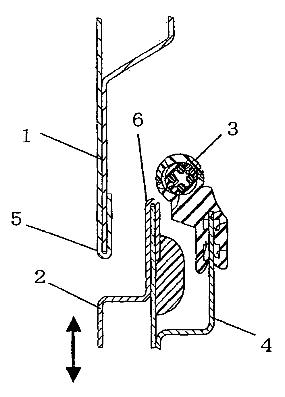
TECHNICAL FIELD [0001] The present invention relates to a moving device having a safety function against an unnecessary contact of an object. In addition, the present invention relates an opening and closing control device for controlling the opening and closing of a moving body by detecting that a moving body catches a certain object in a self-propelled running device, automotive power window, electric sliding door and electric sunroof, and an automatic door of a building. BACKGROUND ART [0002] A conventional moving device will be described using FIGS. 7 and 8. FIG. 7 is an external view of an automobile equipped with a sliding door, and FIG. 8 is a sectional view taken along the line A-A in FIG. 8. In the figures, reference numeral 1 denotes a body portion (a door part at a side of a front passenger seat in FIG. 7) of a vehicle body, 2 denoting a sliding door,3 a pressure sensor, 4 a support portion for supporting the pressure sensor 3 on the sliding door 2, and 5 and 6 flanges. T...

Claims


Application Information

Patent Timeline
Patent Type & Authority Applications(United States)
IPC IPC(8): E05F15/20E05F15/00G01L1/16G01L19/12
CPCE05Y2400/452E05Y2400/59E05Y2400/816E05F15/42G01L1/16G01L19/12E05F15/00E05Y2900/531E05Y2400/83
Inventor UEDA, SHIGEKIOGINO, HIROYUKIKASAI, ISAO
Owner PANASONIC CORP
Learn More