
Mini-refresh processor recovery as bug workaround method using existing recovery hardware

a technology of recovery hardware and micro-refresh processor, applied in the field of data processing system, can solve the problems of not all bugs are easy to work around, failure to work around, corrupted architected state, etc., and achieve the effect of optimizing (reducing) performance impact and enabling power saving states throughout the processor

Inactive Publication Date: 2006-08-17
IBM CORP
View PDF51 Cites 58 Cited by
  • Summary
  • Abstract
  • Description
  • Claims
  • Application Information

AI Technical Summary

Benefits of technology

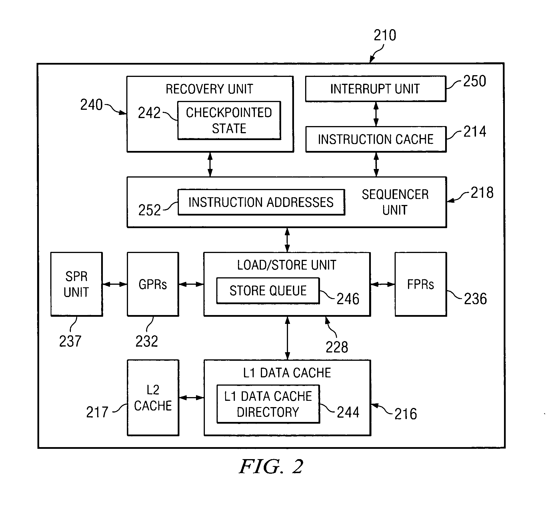
[0009] The present invention is a method in a data processing system for avoiding a microprocessor's design defects and recovering a microprocessor from failing due to a design defect. The method is comprised of the following steps: The method detects and reports a plurality of events which warn of an error. Then the method locks a current checkpointed state (the last known good execution point in the instruction stream) and prevents a plurality of instructions not checkpointed from checkpointing. After that, the method releases a plurality of checkpointed state stores to a L2 cache, and drops a plurality of stores not checkpointed. Next, the method blocks a plurality of interrupts until recovery is completed. Then the method disables the power savings states throughout the processor. E.g. Forces clocks to idle circuits in a low-power state. After that, the method disables an instruction fetch and an instruction dispatch. Next, the method sends a hardware reset signal. Then the method restores a plurality of selected registers from the current checkpointed state. Next, the method fetches a plurality of instructions from a plurality of restored instruction addresses. Then the method resumes a normal execution after a programmable number of instructions.
[0010] One may note the similarity to the instruction retry recovery sequence, but with key differences. Mini-refresh, unlike full recovery, only restores a selected subset of the architected state and does not necessarily invalidate all caches and translation buffers because the coherency with the system has not necessarily been lost. The circuits are presumed functioning properly, and a functional reset is only required for predictably backing up the state of the processor, not for clearing an unpredictable error state from the circuitry. The processor is not necessarily logically removed from a symmetric multi-processing (SMP) system, so incoming invalidates to the processor are still monitored, performed, and responded to. The elements of the reduced performance mode operation are independently selected for the mini-refresh to further optimize (reduce) the performance impact. Finally, thresholding is not done for mini-refresh, and instead forward progress is guaranteed by disabling re-entry to the mini-refresh sequence until after progression beyond reduced execution mode.

Problems solved by technology

However, not all bugs are easy to work around, especially if they cannot be detected and preemptively prevented from corrupting the architected state of the machine before evasive action can be taken.
However, these techniques are not always successful to work around all classes of bugs, and bugs cannot always be detected in time to stop writeback of registers with incorrect data, thus corrupting the architected state.
This method is often successful, however is slow because all architected state is restored and measurably hurts performance because the level 1 cache and buffers are empty and must be reloaded from the memory subsystem.
If instruction retry recovery was invoked for a frequent (every several seconds) event, the performance penalty could be large enough that the customer would realize measurable performance loss, which is unacceptable for a successful workaround to be employed.

Method used


Image

  • Mini-refresh processor recovery as bug workaround method using existing recovery hardware
  • Mini-refresh processor recovery as bug workaround method using existing recovery hardware
  • Mini-refresh processor recovery as bug workaround method using existing recovery hardware

Examples


Embodiment Construction

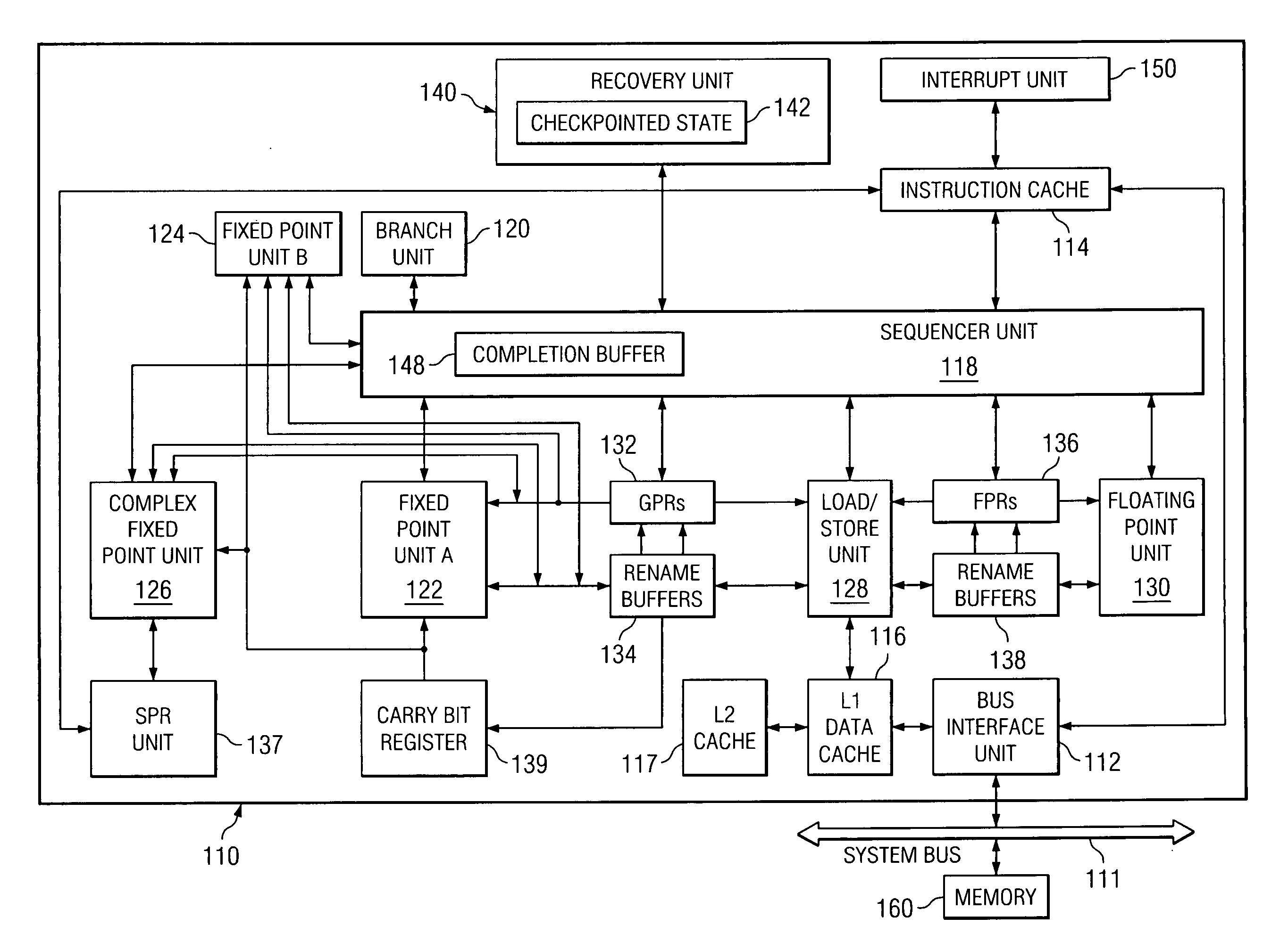
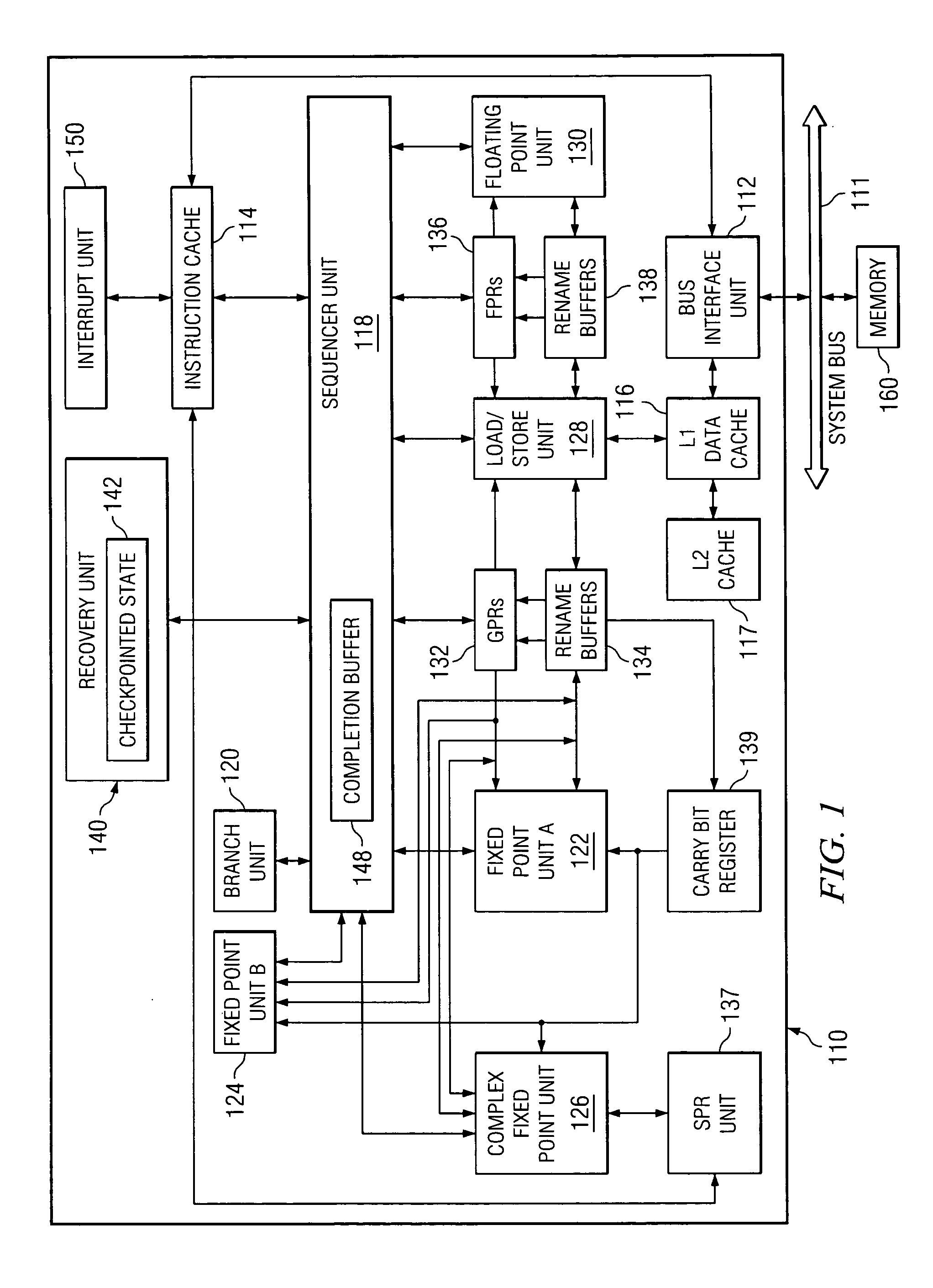
[0016]FIG. 1 is a block diagram of a processor 110 system for processing information according to the preferred embodiment. In the preferred embodiment, processor 110 is a single integrated circuit superscalar microprocessor. Accordingly, as discussed further herein below, processor 110 includes various units, registers, buffers, memories, and other sections, all of which are formed by integrated circuitry. Also, in the preferred embodiment, processor 110 operates according to reduced instruction set computer (“RISC”) techniques. As shown in FIG. 1, a system bus 111 is connected to a bus interface unit (“BIU”) 112 of processor 110. BIU 112 controls the transfer of information between processor 110 and system bus 111.

[0017] BIU 112 is connected to an instruction cache 114 and to a data cache 116 of processor 110. Instruction cache 114 outputs instructions to a sequencer unit 118. In response to such instructions from instruction cache 114, sequencer unit 118 selectively outputs inst...


PUM


Abstract

A method in a data processing system for avoiding a microprocessor's design defects and recovering a microprocessor from failing due to design defects, the method comprised of the following steps: The method detects and reports of events which warn of an error. Then the method locks a current checkpointed state and prevents instructions not checkpointed from checkpointing. After that, the method releases checkpointed state stores to a L2 cache, and drops stores not checkpointed. Next, the method blocks interrupts until recovery is completed. Then the method disables the power savings states throughout the processor. After that, the method disables an instruction fetch and an instruction dispatch. Next, the method sends a hardware reset signal. Then the method restores selected registers from the current checkpointed state. Next, the method fetches instructions from restored instruction addresses. Then the method resumes a normal execution after a programmable number of instructions.

Description

CROSS-REFERENCE TO RELATED APPLICATION [0001] The present application is related to co-pending application entitled “PROCESSOR INSTRUCTION RETRY RECOVERY”, Ser. No. ______, attorney docket number AUS920040996US1, filed on even date herewith. The above application is assigned to the same assignee and is incorporated herein by reference.BACKGROUND OF THE INVENTION [0002] 1. Technical Field [0003] The present invention generally relates to an improved data processing system and, in particular, to a method, apparatus, or computer program product for limiting performance degradation while working around a design defect in a data processing system. Still more particularly, the present invention provides a method, apparatus, or computer program product for enhancing performance of avoiding a microprocessor's design defects and recovering a microprocessor from failing due to a design defect. [0004] 2. Description of Related Art [0005] A microprocessor is a silicon chip that contains a centr...

Claims


Application Information

Patent Timeline
Patent Type & Authority Applications(United States)
IPC IPC(8): G06F9/30
CPCG06F9/3851G06F9/3863
Inventor FLOYD, MICHAEL STEPHENLEITNER, LARRY SCOTTLEVENSTEIN, SHELDON B.SWANEY, SCOTT BARNETTTHOMPTO, BRIAN WILLIAM
Owner IBM CORP
Learn More